INFICON SQM-242 Thin Film Deposition Controller Card Software Operating Manual User Manual
Page 71
4 - 3
IP
N 07
4-
55
1-
P1
A
SQS-242 Operating Manual
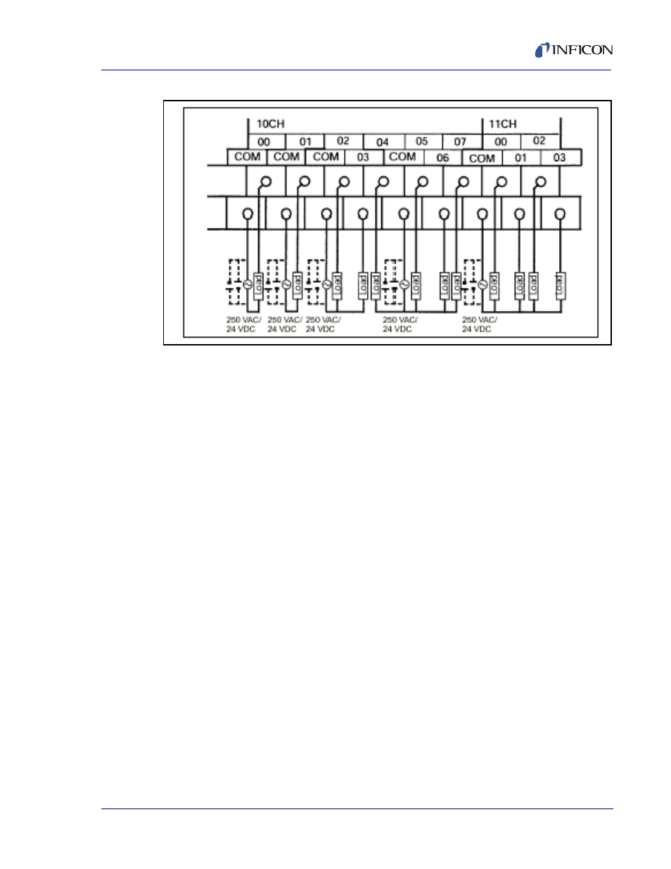
Figure 4-3 Omron PLC Output Wiring
Omron PLC output wiring is illustrated in
. Notice that some relays (i.e.,
02/03 and 04/05/06/07) share a common terminal.
NOTE: The internal 24 V (dc), .3 A supply of the Omron PLC is NOT adequate to
serve as the supply shown in the diagram above.
Indexer I/O: Indexers from different manufacturers use a variety of pocket
decoding schemes. The PLC monitor program adapts information from the
SQS-242 program to a specific indexer. The two most common indexer decoding
schemes are illustrated below.
Binary Pocket Select: Each pocket requires a dedicated relay. That is 8 pockets
require 8 relays. The CPM2A-Basic PLC monitor program assigns relays 11.00 to
11.03 to operate a 4 pocket indexer of this type.
Binary Coded Pocket Select: Pockets are selected by a value that is the binary
representation of the pocket. That way fewer relays are required. For example, 16
pockets can be selected with only four relays. The CPM2A-BCD monitor program
assigns relays 11.00 to 11.03 to this function.
Please contact INFICON for information on your indexer.
Other Digital I/O: Depending on the PLC model used, additional relay and input
pins are available for other functions (i.e., source indexer operation). Please
contact INFICON.