Warning – INFICON SQM-242 Thin Film Deposition Controller Card Software Operating Manual User Manual
Page 32
3 - 2
IP
N 07
4-
55
1-
P1
A
SQS-242 Operating Manual
WARNING
Care should be exercised to route cables as far as
practical from other cables that carry high voltages or
generate noise. This includes other line voltage cables,
wires to heaters that are SCR-controlled, and cables to
source power supplies that may conduct high transient
currents during arc down conditions
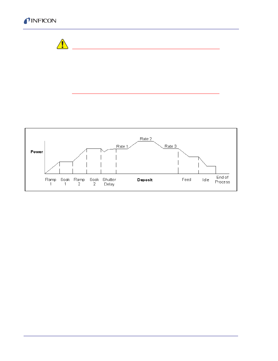
A typical deposition cycle for a thin film is shown in
broken into three distinct phases: pre-conditioning (ramp/soak), deposition, and
post-conditioning (feed/idle)
Figure 3-2 Typical Deposition Cycle
During pre-conditioning, power is applied to prepare the source material for
deposition. The first ramp/soak preconditioning phase is used to bring the material
to a uniform molten state. The second ramp/soak phase is typically set to a power
that is near the desired deposition rate.
When pre-conditioning ends, PID rate control of deposition begins. Initially, the
substrate material may remain shuttered until the desired deposition rate is
achieved (shutter delay). Once the control loop achieves the desired rate, the
shutter opens and deposition begins. Multiple deposition rates (rate ramps) can be
programmed.
When the desired thickness is reached, the evaporation source is set to feed or idle
power. At this point the process may be complete, or deposition of another film
layer may begin. Up to six separate films can be codeposited within a single layer.
There is no practical limit to the total number of processes, layers, or materials that
can be stored in the process database.