7 comm tab – INFICON SQM-242 Thin Film Deposition Controller Card Software Operating Manual User Manual
Page 59
3 - 29
IP
N 07
4-
55
1-
P1
A
SQS-242 Operating Manual
Max/Init/Min Frequency: The frequency values for the quartz crystal sensors used
as inputs to the SQM-242. Typical values are Max=6.1, Init=6.0, Min=5.0. Sensor
readings outside the min/max values cause a Sensor Fail error.
Filter: Sets the number of readings used in the reading filter. A low setting gives
rapid response to process changes, high settings give smoother graphs.
Last Output: Limits the maximum number of outputs shown on the main dialog
box.
Continuous: Check this box to have the graph continuously display data for each
phase of the deposition cycle. Uncheck this box to clear the graph at the end of the
preconditioning, deposition, and post conditioning phases.
Graph X Axis: Sets the width of the X axis during deposition, normally 100
seconds. Whatever width is selected, the graph automatically scrolls the X axis as
required. Due to screen resolution, setting a width of more than 10 minutes (600
seconds) may cause some data points to not be plotted.
Graph Y Axis: Sets the Y axis Rate graph maximum value during deposition.
Setting the value to 0 causes the Y axis to automatically scale to the highest rate
displayed.
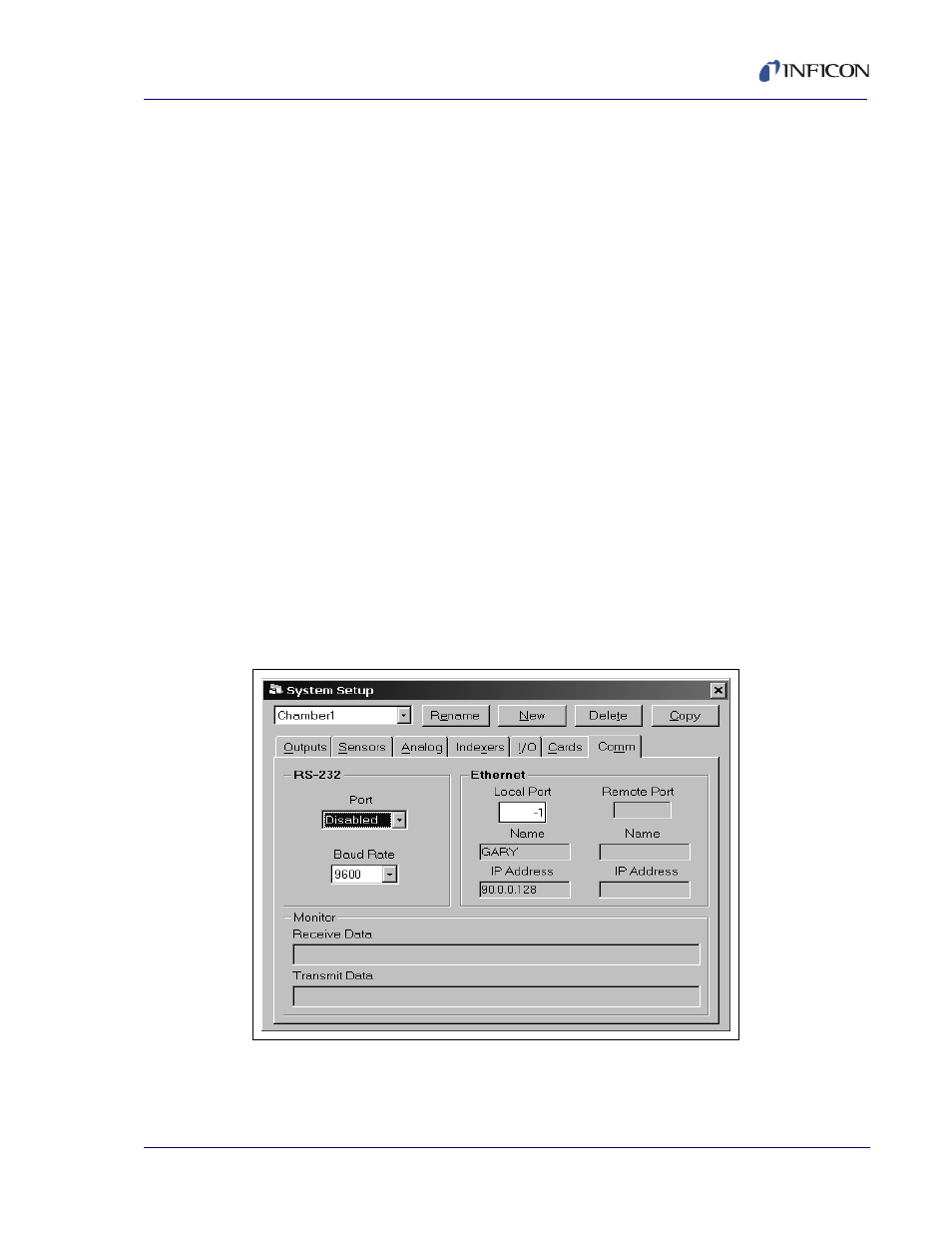
3.5.4.7 Comm Tab
The SQS-242 software can be controlled by another computer through an RS-232
or Ethernet connection. See
for more details.
Figure 3-24 Comm tab
RS-232 Port: Selects the comm port used for serial communications with another
computer. The Comm Port dropdown box lists available ports.