3 electrical, Figure 5-2 – INFICON STM-2XM 2-Channel Rate/Thickness Monitor User Manual
Page 83
5 - 3
PN
07
4-
61
4-
P1
A
STM-2XM Operating Manual
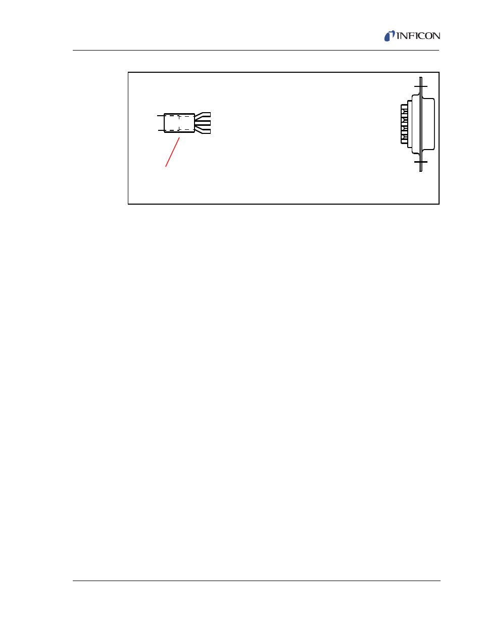
Figure 5-2 PN 783-506-000 cable for RS-485
The RS-485 communications interface must be wired properly with the same baud
rate used for all instruments and a unique SMDP address used for each connected
instrument for communication to occur. A message will not be acknowledged, and
the software will timeout if any of these conditions are not met.
5.3 Electrical
The STM-2XM SMDP interface is two-wire RS-485 providing a single master,
multi-slave, half-duplex network. STM-2XM can also implement this protocol over
an RS-232 interface. This allows STM-2XM to be used for RS-232 or RS-485
networks and makes an upgrade path from point-to-point.
In point-to-point RS-232 mode, the transmit and receive data lines are converted
to logic levels with a standard RS-232 transceiver.
In RS-485 bus mode, a two-wire bus uses lines designated as inverting and
non-inverting and carries complementary Transistor-Transistor Logic (TTL) level
differential signals, time-shared (half-duplex) for messages to and from the master.
When the line is idle, the non-inverting signal line is at a TTL high.
PIN 2 - GREEN (RS-232 TXD) [RS-485 Inverting Signal]
PIN 3 - RED (RS-232 RXD) [RS-485 Non-inverting Signal]
PIN 5 - ORANGE (Signal GND) [Signal GND]
PN 783-506-000
RS-232 Cable