4 deposition system installation, 1 sensor head installation – INFICON STM-2XM 2-Channel Rate/Thickness Monitor User Manual
Page 35
2 - 9
PN
07
4-
61
4-
P1
A
STM-2XM Operating Manual
2.4 Deposition System Installation
2.4.1 Sensor Head Installation
Install the sensor as far as possible from the evaporation source (a minimum of
25.4 cm (10 in.)) while still being in a position to accumulate thickness at a rate
proportional to accumulation on the substrate.
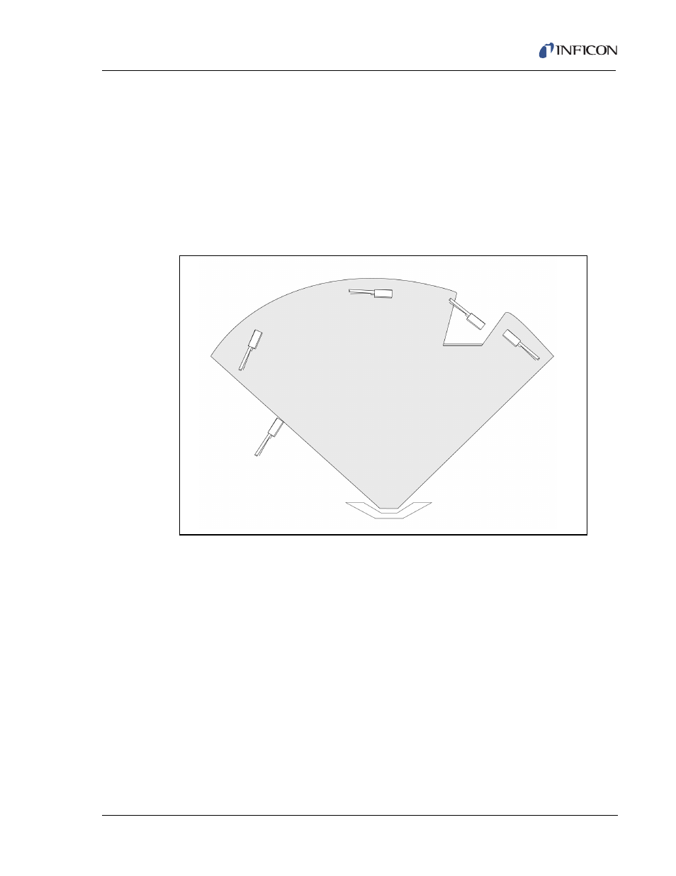
shows proper and
improper methods of installing sensors.
NOTE: For best process reproducibility, rigidly support the sensor so that it cannot
move during maintenance and crystal replacement.
Figure 2-7 Sensor installation guidelines
To guard against spattering, use a source shutter to shield the sensor during initial
soak periods. If the crystal is hit with a particle of molten material, it may be
damaged and stop oscillating. Even in cases when the crystal does not completely
stop oscillating, it may immediately become unstable or instability may occur
shortly after deposition begins.
Plan the installation to ensure that there are no obstructions blocking a direct path
between the sensor and the source. Install sensors in such a manner that the
center axis of the crystal is aimed directly at the source to be monitored. Verify that
the angle of the sensor location (with reference to the source) is well within the
evaporant stream. If the sensor is not perpendicular to the source, the coating on
the crystal will be tapered and diminished crystal life can result.
NOTE: In many cases installing multiple sensors to monitor one source can
improve thickness accuracy for the product. The recommendations for
multiple sensors are the same as for a single sensor installation, and the
locations chosen should be as defined above.
Correct
Incorrect
Correct
Incorrect
Incorrect
Obstruction
Source