SkyTrak 6036 Service Manual User Manual
Page 230
Section 10.
Electrical System
10-36
Model 6036 S/N 9B0499 and Before
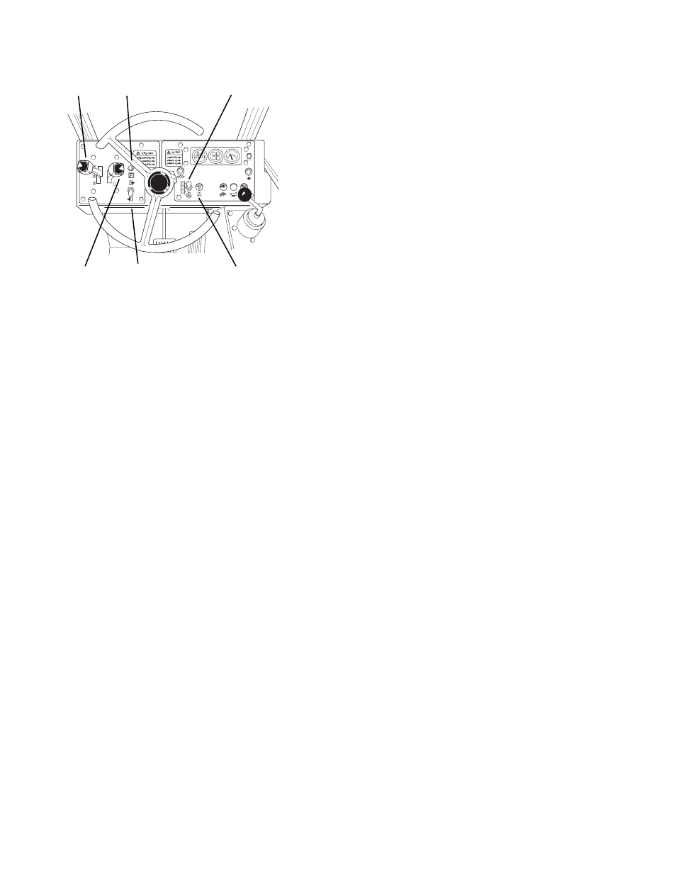
TRAVEL
SELECT
LEVER
PARK
LOCK
LIGHT
STEERING
SELECT
SWITCH
PARK
LOCK
SWITCH
RANGE
SELECT
LEVER
Fig. 10.43 Control Panel
a.
Removal
1.
Engage the park lock, place the travel select
lever in neutral, and turn the ignition switch to
OFF.
2.
Disconnect negative (–) cable (2, Fig. 10.38)
from the batteries.
3.
Unlock and open the right engine access door
to gain access to the fuel injection pump.
4.
Tag and remove electric wires.
5.
A plunger and spring may fall from the sole-
noid when it is removed from the fuel injection
pump. Be prepared to catch these parts when
you remove the solenoid. Use an appropriate
wrench to turn the solenoid counterclockwise.
6.
Discard the O-ring.
b. Disassembly
Do not disassemble the fuel run solenoid.
c.
Cleaning and Drying
Without submerging the electrical components,
clean the fuel run solenoid using a approved
solvent and dry using a clean lint-free cloth.
d. Inspection and Replacement
1.
Prepare to test the fuel run solenoid by
assembling the valve at a bench.
2.
Inspect the rubber tip on the plunger and
replace plunger if tip is worn.
3.
Lubricate valve core and plunger using clean
fuel oil.
4.
Place the spring and plunger in the solenoid.
5.
Energize the solenoid using 12 Vdc to see if
the plunger retracts. Replace fuel run sole-
noid if it doesn’t retract.
e.
Installation
1.
Clean exterior of fuel injection pump.
2.
Install a new O-ring on the fuel run solenoid.
3.
Remove protective plug from fuel injection
pump.
4.
With spring and plunger in solenoid, turn fuel
run solenoid into fuel injection pump, being
careful to avoid cross threading. Tighten until
snug.
5.
Connect electric wires and connect negative
cable to batteries.
6.
Close and lock the engine access door.
7.
Prepare to test fuel run solenoid by clearing
personnel and any obstructions from the area
around the forklift.
8.
Start the engine.
• If engine starts the solenoid is functioning.
• If engine fails to start, solenoid may have
a poor ground connection. Check voltage
at solenoid.
9.
Check for fuel oil leakage around solenoid.
10.7.4
Park Lock Switch
The park lock switch, Fig. 10.43, has two posi-
tions, engaged and disengaged. To engage, lift
cover and flip lever up. To disengage, lower
switch cover.
a.
Removal
1.
Disconnect negative (–) cable (2, Fig. 10.38)
from batteries.
2.
Prepare to remove park lock switch, Fig.
10.43, by removing the lower panel which is
located below the switch.
3.
Tag and disconnect electric wires from the
switch.
4.
Remove hex nut cap seal and the hex nut
which secures switch to left front console
panel.
5.
Remove switch guard and decal.
b. Disassembly
Do not disassemble the park lock switch.
WINDSHIELD
WASHER/WIPER
CONTROL
OA0031