Warning – SkyTrak 6036 Service Manual User Manual
Page 210
Section 10.
Electrical System
10-16
Model 6036 S/N 9B0499 and Before
2.
If the starter is to be reinstalled, clean the
exterior of the starter with an approved solvent
without submerging the starter or allowing the
solvent to contact the bushings.
3.
Dry the starter using a clean, lint-free cloth.
e.
Inspection and Replacement
You can bench test a starter by using battery
jumper cables. Connect the negative cable to the
starter housing and touch the positive cable to the
positive connection on the starter motor. The
motor should spin if it is good.
f.
Starter No Load Test
General Information
1.
The No Load Test is done with the starter
removed from the forklift.
2.
If the starter drive doesn’t slide freely on the
armature shaft, clean and repair as required.
3.
If the armature doesn’t rotate freely, disas-
semble the starter and repair as required
before doing the No Load Test.
Test Equipment
1.
A Sun Electric VAT-33 Tester, an equivalent
tester, or separate pieces of test equipment.
2.
A hand held tachometer.
3.
A remote starter button to actuate the starter.
4.
A fully charged 12 V battery.
Test Procedure
Connect the test equipment according to this
procedure and the manufacturer’s instructions. If
the VAT-33 tester is being used:
1.
Select the 0 to 100 A range.
2.
Select the 18 to 40 V range.
3.
Move the volt lead switch to the EXT position.
4.
Turn the load control to the OFF position.
Fasten the starter in a vise or use another
method to prevent the starter from moving; this
is essential to prevent personal injury.
Warning !
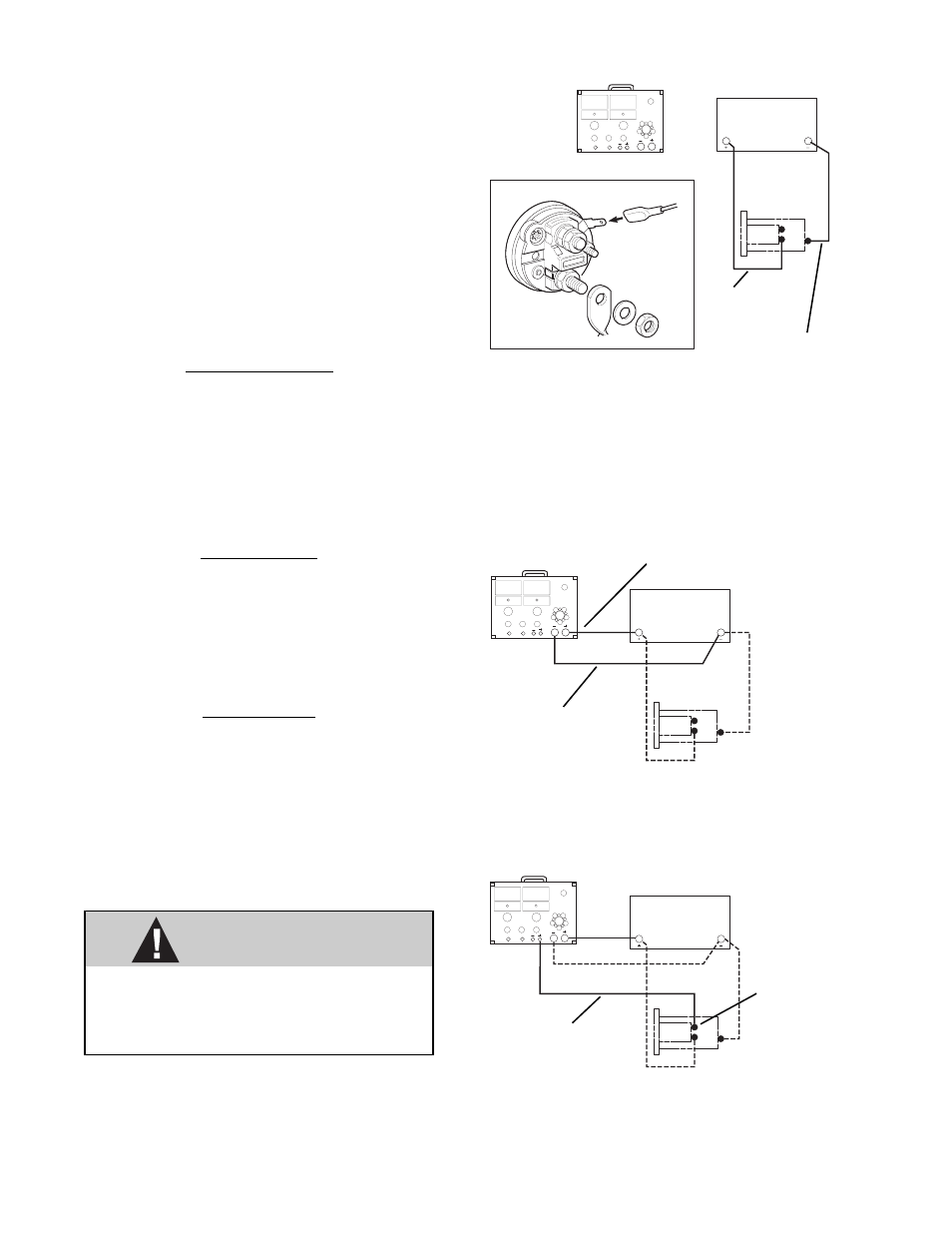
Fig. 10.18 Red Voltmeter Lead
7.
Connect the red voltmeter lead to the motor
terminal on the starter solenoid, Fig. 10.18.
Fig. 10.17 Positive and Negative Load Cables
6.
Connect the positive load cable to the positive
post of the battery. Connect the negative load
cable to the negative post, Fig. 10.17.
Fig. 10.16 Positive and Negative Battery Cables with
End View of Starter Solenoid
5.
Connect the positive battery cable to the
battery terminal on the starter solenoid and the
negative battery cable to the mounting flange
of the starter, Fig. 10.16.
POSITIVE
BATTERY
CABLE
NEGATIVE
BATTERY
CABLE
POSITIVE LOAD CABLE
NEGATIVE LOAD
CABLE
RED VOLTMETER
LEAD
MOTOR
TERMINAL
MA0991
MA1001
MA1011