SkyTrak 6036 Service Manual User Manual
Page 159
Model 6036 S/N 9B0499 and Before
9-46
Section 9.
Hydraulic System
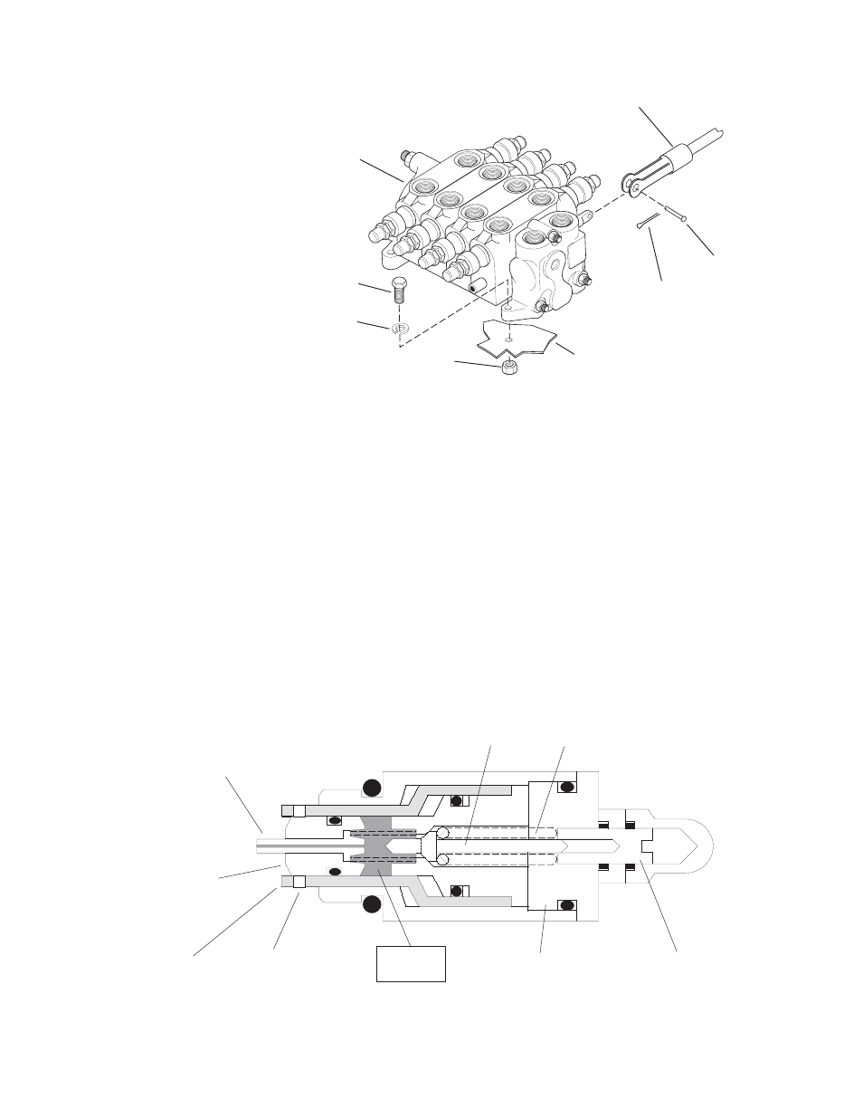
PISTON
PILOT
POPPET
PILOT
SPRING
ADJUSTMENT
SCREW
PLUG
TO
RESERVOIR
RELIEF VALVE
POPPET
CHECK VALVE
POPPET
RELIEF
AREA
1
2
3
4
5
6
7
FRAME
The relief valve setting is determined by the
compression of the pilot spring as set by the
adjustment screw. When the pressure exceeds
the relief setting, the pilot poppet acts against the
poppet spring to unseat. The fluid then flows
around the pilot poppet through cross-drilled holes
in the plug to the reservoir; some pressure is
relieved.
Due to the reduced pressure, the piston seats
against the pilot poppet. This shuts off fluid flow
through the valve and causes a low pressure area
internally. The differential pressure between the
supply pressure and the internal pressure causes
the relief valve poppet to unseat and fluid flows to
the reservoir thus relieving the pressure.
If low supply pressure should occur due to pump
cavitation, the check valve poppet will unseat and
allow fluid to flow back to the supply from the
reservoir.
Refer to paragraph 9.1 for information on relief
valve functions and testing.
Fig. 9.23 Main Control Valve Installation
1.
Cotter Pin
2.
Retaining Pin
3.
Locknut
4.
Washer
5.
Capscrew
6.
Main Control Valve
7.
Linkage
Fig. 9.24 Relief Valve Sectional View
MA0641
MA0652