SkyTrak 6036 Service Manual User Manual
Page 168
9-55
Model 6036 S/N 9B0499 and Before
Section 9.
Hydraulic System
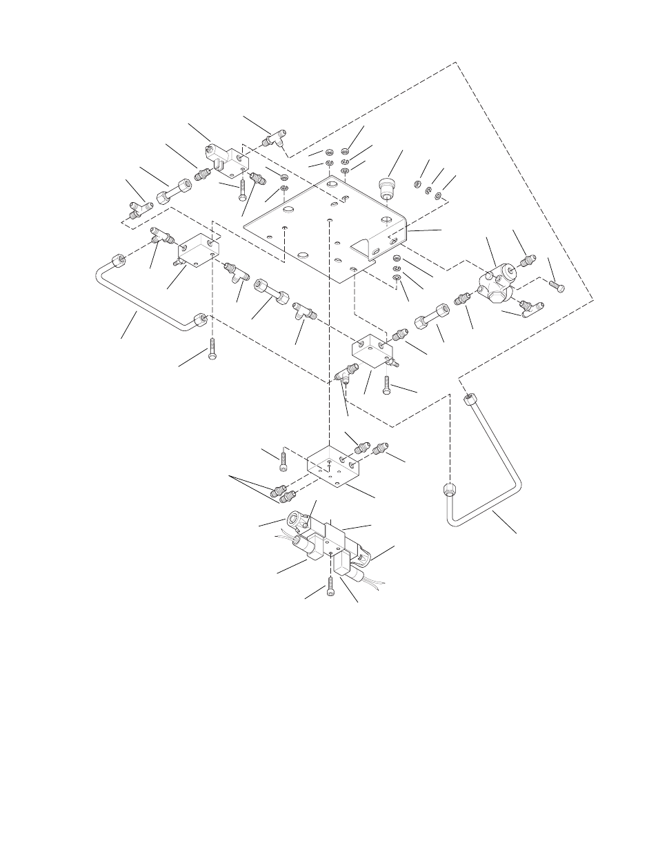
Fig. 9.33 Valve Plate Assembly - Underside View, Exploded S/N 8G0236 and After
B
J
A
L
H
G
E
F
1
2
3
4
5
6A
6
7
8
9
10
11
11
12
13
14
15
16
17
16
16
18
19
19
20
21
22
24
25
26
27
28
18
30
29
1A
1B
31
11
21
19
20
21
13
19
21
12
23
6
M
K
1.
Steer Select Valve
1A. Electrical Connector
1B. Solenoid (2)
1C. Screw (4)
2.
Park Lock Release Valve
3.
Sequence Valve
4.
Pressure Reducing Valve
5.
Relief Valve
6.
Connector (4)
7.
Connector (1)
8.
Connector (1)
9.
Run Tee (1)
10. Connector
11. Run Tee (3)
12. Run Tee (12)
13. Connector (2)
14. Branch Tee
15. Tube Assembly
16. Tube Assembly (3)
17. Tube Assembly
18. Capscrew (2)
19. Lock Washer (8)
20. Flat Washer
21. Hex Nut (8)
22. Capscrew (4)
23. Capscrew (2)
24. Capscrew (2)
1B
1C
1A
C D
MA0741
25. Lock Washer (2)
26. Flat Washer (2)
27. Hex Nut (2)
28. Capscrew (2)
29. Rubber Mount (4)
30. Mounting Plate
31. Subplate
HOSE CONNECTIONS
A.
To Brake Valve Return
B.
To Park Lock
C.
To Rear Brake Cylinder
D.
To Rear Brake Cylinder
E.
To Steering Unit
F.
To Front Steering Cylinder
G.
To Control Valve
H.
To Steering Unit Outlet
I.
To Steering Unit Inlet
J.
To Brake Valve Inlet
K.
To Reservoir
L.
To Small Pump Inlet
M.
To Emergency Pump Outlet