SkyTrak 6036 Service Manual User Manual
Page 174
9-61
Model 6036 S/N 9B0499 and Before
Section 9.
Hydraulic System
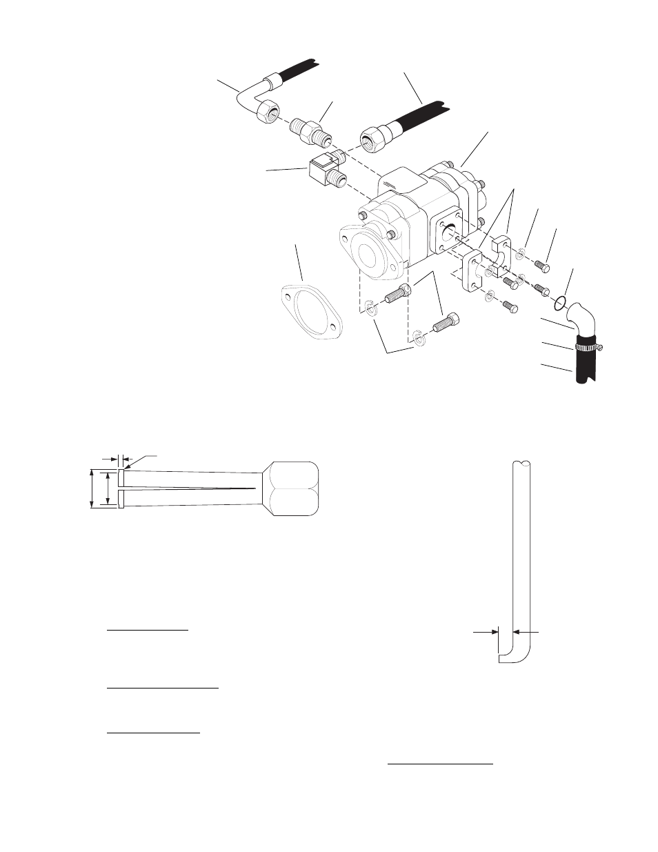
1.
Hose Clamp
2.
Inlet Hose
3.
Elbow
4.
Clamp Half (2)
5.
Capscrew (4)
6.
Lock Washer (4)
7.
O-ring
8.
Small Pump Outlet Hose
9.
Large Pump Outlet Hose
10. Connector
11. Elbow
12. Capscrew (2)
13. Lock Washer (2)
14. Main Tandem Pump
15. Pump Gasket
Fig. 9.37 Main Tandem Pump Installation
0.015" R. MAXIMUM
C
B
A
A = 0.980/0.970"
B = 0.875/(REF)"
C = 0.100/0.090"
Fig. 9.38 Bushing Puller
2.
A seal removal tool made by heating the tip of
an old screwdriver and bending it as shown in
Fig. 9.39. Grind off the tip to fit the notch
behind the shaft seal.
3.
A bushing installation tool made from A.I.S.I.
8620 Heat Treated Bearing Quality Steel as
shown in Fig. 9.40.
4.
A special steel sleeve made from bar stock
which is 1-1/8 or 1-1/4" diameter by 4-5/8", as
shown in Fig. 9.41. This sleeve is used to
insert the drive shaft through the lip seal
without damage.
1/4 INCH
Fig. 9.39 Seal Removal Tool
5.
A lip seal installation bar made from bar stock
which is 1-3/4" in diameter by 2" long. Break
edges slightly.
8
10
9
11
14
4
6
5
7
3
2
1
12
19
13
MA0781
MA0801
MA0791