2 boom extend/retract – SkyTrak 6036 Service Manual User Manual
Page 118
Section 9.
Hydraulic System
9-5
Model 6036 S/N 9B0499 and Before
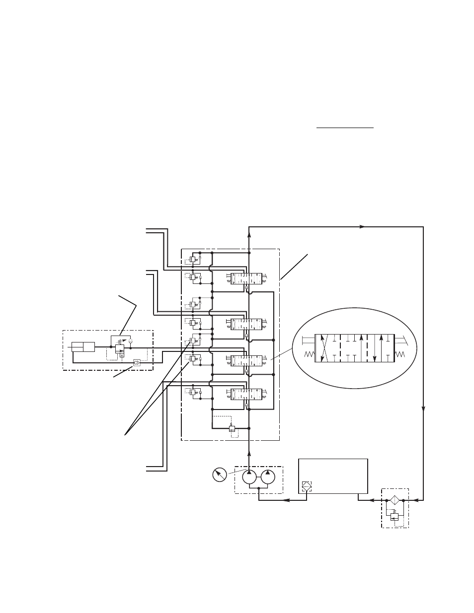
Fig. 9.3 Boom Extend Circuit
5.
Starting at the fully raised position, lower the
boom at full engine speed. The time required
to lower the boom to its lowest position should
be 8 to 10 seconds (no load).
6.
Repeat steps 4 and 5 to recheck performance.
7.
If the boom raise/lower circuit test does not
meet performance requirements, locate the
cause of the problem and correct before
putting the vehicle into service.
9.1.2 Boom Extend/Retract
a.
Description
Hydraulic pressure is applied in the boom extend/
retract circuit by the 30 gpm section (rear half) of
the tandem pump, which draws its fluid through a
suction stainer in the reservoir, Fig. 9.3. Supply
pressure is directed to either side of the extend/
retract cylinder piston by the shifting of a spool in a
directional control valve found in the main control
valve assembly. The spool is shifted by the
operator joystick and its associated control cable.
The joystick positions for extending or retracting
the boom are as follows:
Center Position
When the joystick is placed in the center or neutral
position, the directional control valve spool is
positioned so that supply pressure is directed
through ports F to C, Fig. 9.3, to the return filter
and reservoir. If the return filter becomes
clogged, hydraulic oil will bypass the filter when the
pressure reaches 10 to 15 psi
(0,7 to 1,03 bar).
MAIN CONTROL
VALVE
A B C A B C A B C
STRAINER
RETURN
FILTER
TANDEM
PUMP
PILOT OPERATED
CHECK VALVE
DIRECTIONAL CONTROL VALVE POSITIONS
CENTER
D E F D E F D E F
TO FRAME TILT
CYLINDER
TO GRILLE TILT AND
SLAVE CYLINDERS
BOOM EXTEND
CYLINDER
COUNTERBALANCE
VALVE
EXTEND
BOOM EXTEND PORT
RELIEF VALVES
TO BOOM HOIST
CYLINDER
0-4000 psi
PRESSURE
GAUGE
RESERVOIR
15
GPM
30
GPM
RETRACT
RETRACT
EXTEND
MA0441