5 brake circuits – SkyTrak 6036 Service Manual User Manual
Page 127
Section 9.
Hydraulic System
Model 6036 S/N 9B0499 and Before
9-14
M
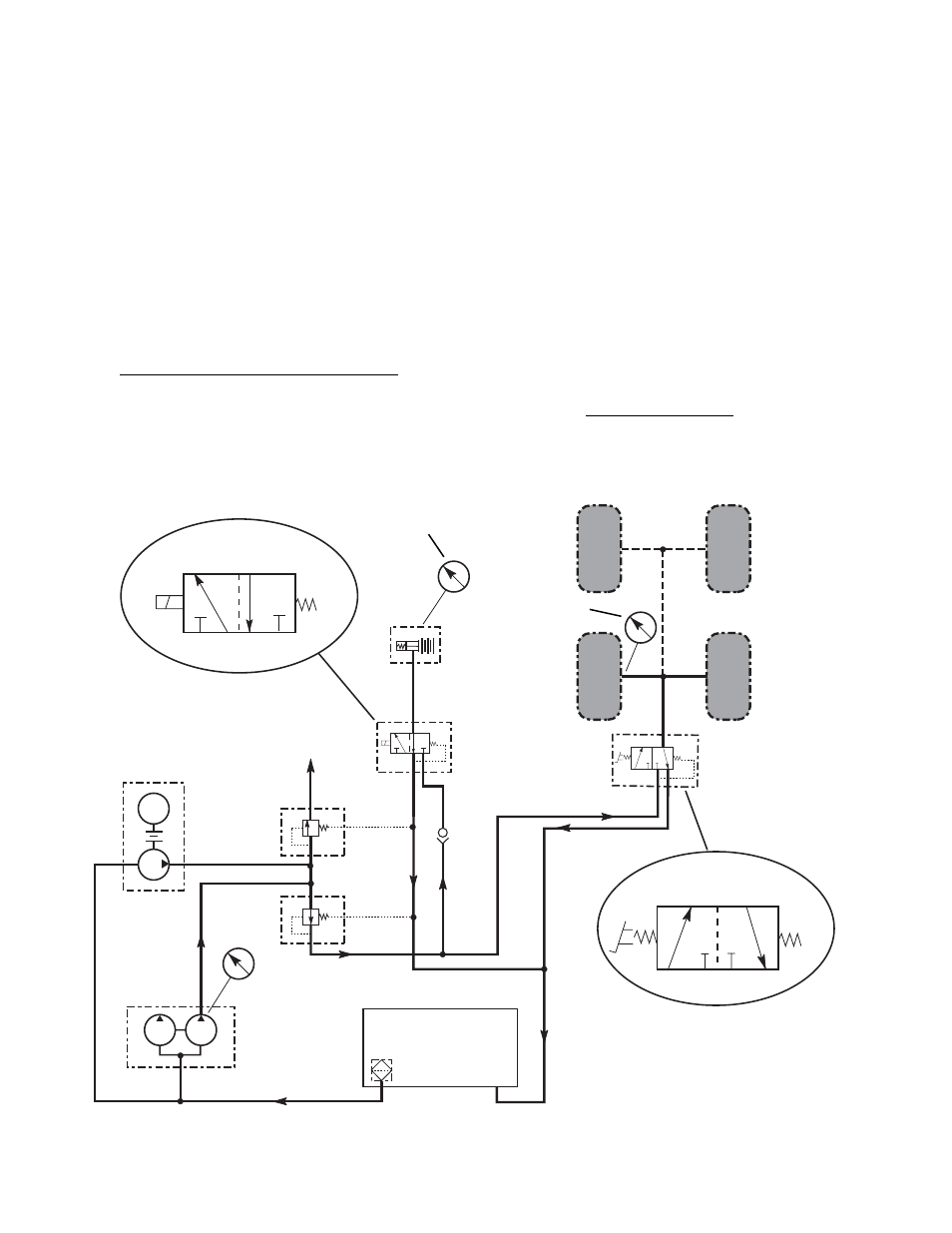
9.1.5 Brake Circuits
a.
Description
Hydraulic pressure is normally applied in the
service and park lock brake circuits by the 15 gpm
section (front half) of the tandem pump, which
draws its fluid through a suction strainer in the
reservoir, Fig. 9.6. A pressure of 575 ± 25 psi
(39,6 ± 1,7 bar) is maintained on the service
brakes and park lock by the sequence valve. This
pressure is reduced to 525 ± 25 psi (36,2 ± 1,7
bar) at the pressure reducing valve prior to
entering the solenoid-operated park lock release
valve and pedal-operated service brake valve.
Steering and Emergency Brake Pump
The steering and emergency brake pump, Fig.
9.6, provides limited backup hydraulic supply
pressure to the steering and brake circuits in the
event of engine stoppage or tandem pump failure
and during initial start-up before the tandem pump
is fully operational. This pump is driven by an
electric motor; it also draws fluid through the
suction strainer in the reservoir.
The steering and emergency brake pump is
controlled by a oil pressure switch on the engine
which senses the engine oil pressure. When the
ignition switch is in RUN position and the pressure
switch is closed at oil pressure below 4 psi (0,3
bar), the steering and emergency brake pump is
energized and the pump will run. Output of the
pump is 3 gpm at approximately 1500 psi (104
bar). When the pressure rises above 4 psi (0,3
bar), (engine running), the oil pressure switch
opens to stop the steering and emergency brake
pump.
Service Brake Valve
When the brake pedal in the operator’s cab is
not depressed, the brake valve spool is spring-
15
GPM
30
GPM
STEERING AND
EMERGENCY
BRAKE PUMP
SEQUENCE
VALVE
TANDEM
PUMP
STRAINER
PRESSURE
REDUCING
VALVE
0-4000 psi
PRESSURE
GAUGE
PARK LOCK
RELEASE
VALVE
PARK
LOCK
3
GPM
C
TO POWER
STEERING
UNIT
DISENGAGED
ENGAGED
Fig. 9.6 Brake Circuits
SERVICE
BRAKE
VALVE
SERVICE BRAKE VALVE
POSITIONS
RESERVOIR
BRAKES
APPLIED
BRAKES NOT
APPLIED
0-1000 psi
PRESSURE
GAUGE
0-1000 psi PRESSURE
GAUGE INSTALLED IN
PARK LOCK BLEEDER
MA0472
D C
D
A
B
C
D
C
D
A
B