SkyTrak 6036 Service Manual User Manual
Page 164
9-51
Model 6036 S/N 9B0499 and Before
Section 9.
Hydraulic System
5.
Tag and disconnect three hydraulic hoses (4,
Fig. 9.30) from the right side of the service
brake valve. Cap and plug the open hose
connectors.
6.
Remove jam nuts (4, Fig. 9.28), lock washers
(5) and capscrews (6) which secure valve to
the mounting bracket.
7.
Remove the service brake valve from the
machine.
b. Disassembly
1.
Remove ring (1, Fig. 9.29) and boot (2) from
housing (13).
2.
Remove piston (3), shim or shims (4), and
springs (5 and 6) from housing bore.
3.
Carefully remove O-ring (7) to avoid scratch-
ing the housing bore.
4.
Carefully remove retaining ring (8) to avoid
scratching housing bore.
5.
Remove washer (9), plunger (10) and spring
(12) from housing bore.
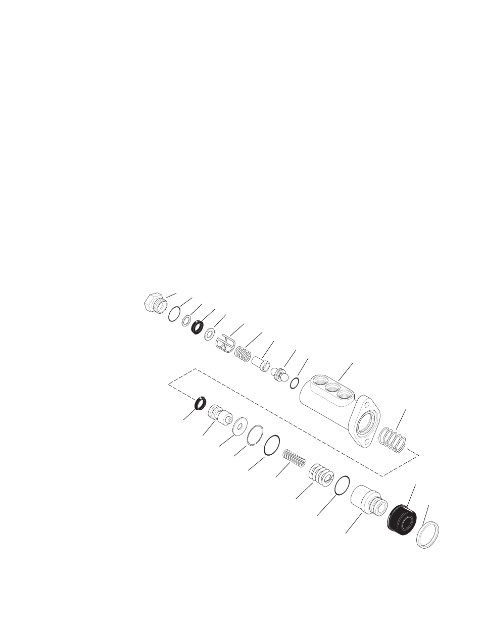
1.
Retaining Ring
2.
Boot
3.
Piston
4.
Shims (as required)
5.
Spring
6.
Spring
7.
O-ring
8.
Retaining Ring
9.
Washer
10. Plunger
11. Cup
12. Spring
13. Housing
14. O-ring
15. Valve and Ball Assembly
16. Guide
17. Spring
18. Sleeve
19. Washer
20. Cup
21. Backup Ring
22. O-ring
23. Plug
Fig. 9.29 Brake Valve Exploded View
1
2
3
4
5
6
7
8
9
10
11
12
13
14
15
16
17
18
19
20
21
22
23
MA0701
6.
Remove cup (11) from plunger (10).
7.
Remove plug (23) from housing (13).
8.
Remove O-ring (22), cup (20) and backup ring
(21) from plug (23).
9.
Remove washer (19), sleeve (18), spring (17)
and guide (16) from the housing bore.
NOTE: Some valves may not have a sleeve (18).
10. Remove valve and ball assembly (15) from
housing bore.
11. Remove O-ring (14) from the valve and ball
assembly.
c.
Cleaning and Drying
Clean all metal parts in an approved cleaning
solvent such as trichlorethylene and blow dry.
d. Inspection, Repair and Replacement
1.
Inspect valve bore for deep grooves or other
damage. If there is any damage to the bore,
replace the entire brake valve.