Warning, 6 engine removal – SkyTrak 6036 Service Manual User Manual
Page 105
Section 8.
Engine
Model 6036 S/N 9B0499 and Before
8-19
1.
Remove the transmission cover and open both
engine access doors.
2.
Lower the boom to the ground.
3.
Remove the counterweight from the rear of the
frame.
4.
Remove the radiator cover.
5.
Remove oil cooler from the rear support and
detach the lines. Catch any excess oil that
drains from cooler and lines. Cap the lines.
6.
Detach and remove the air cleaner system
from the rear support and engine as follows:
Warning
To avoid severe burns, DO NOT attempt this
procedure when the engine, cooling, and
hydraulic systems are hot. Wait until they have
cooled before proceeding.
8.6
ENGINE REMOVAL
Removal from Naturally Aspirated Engine
(a) Loosen clamp that secures the elbow to
the engine inlet manifold.
(b) Loosen clamp that secures the elbow to
the air cleaner assembly.
(c) Remove the nuts, lock washers, washers
and capscrews that secure the air cleaner
mounting band to the forklift frame.
Removal from Turbocharged Engine
(a) Loosen clamp that secures hose to hose
reducer at the air inlet to the turbocharger.
(b) Loosen clamp that secures hose to hump
hose at the air cleaner assembly.
(c) Remove the nuts, lock washers, washers
and capscrews that secure the air cleaner
mounting band to the forklift frame.
7.
Detach the exhaust system from the engine at
exhaust manifold as follows:
(a) Remove the parts attaching tail pipe to
engine and muffler, Fig. 8.23 and 8.24.
(b) Loosen and remove the T-Bolt that secures
the muffler to the engine.
(c) Remove the parts attaching the exhaust
pipe to the exhaust manifold or turbo-
charger, as applicable.
8.
Drain the radiator as follows:
(a) Remove the radiator cap.
(b) Place a container under the radiator
petcock at the bottom left corner of the
radiator.
(c) Open the petcock and allow the coolant to
drain from the radiator.
9.
Disconnect radiator overflow bottle and radiator
hose connections at engine.
10. Remove the radiator, hoses, and shroud.
11. Disconnect the wiring to the backup alarm, Fig.
8.26.
12. Remove the rear support (which is above the
engine between the side frame members) along
with the backup alarm.
1
2
3
4
5
6
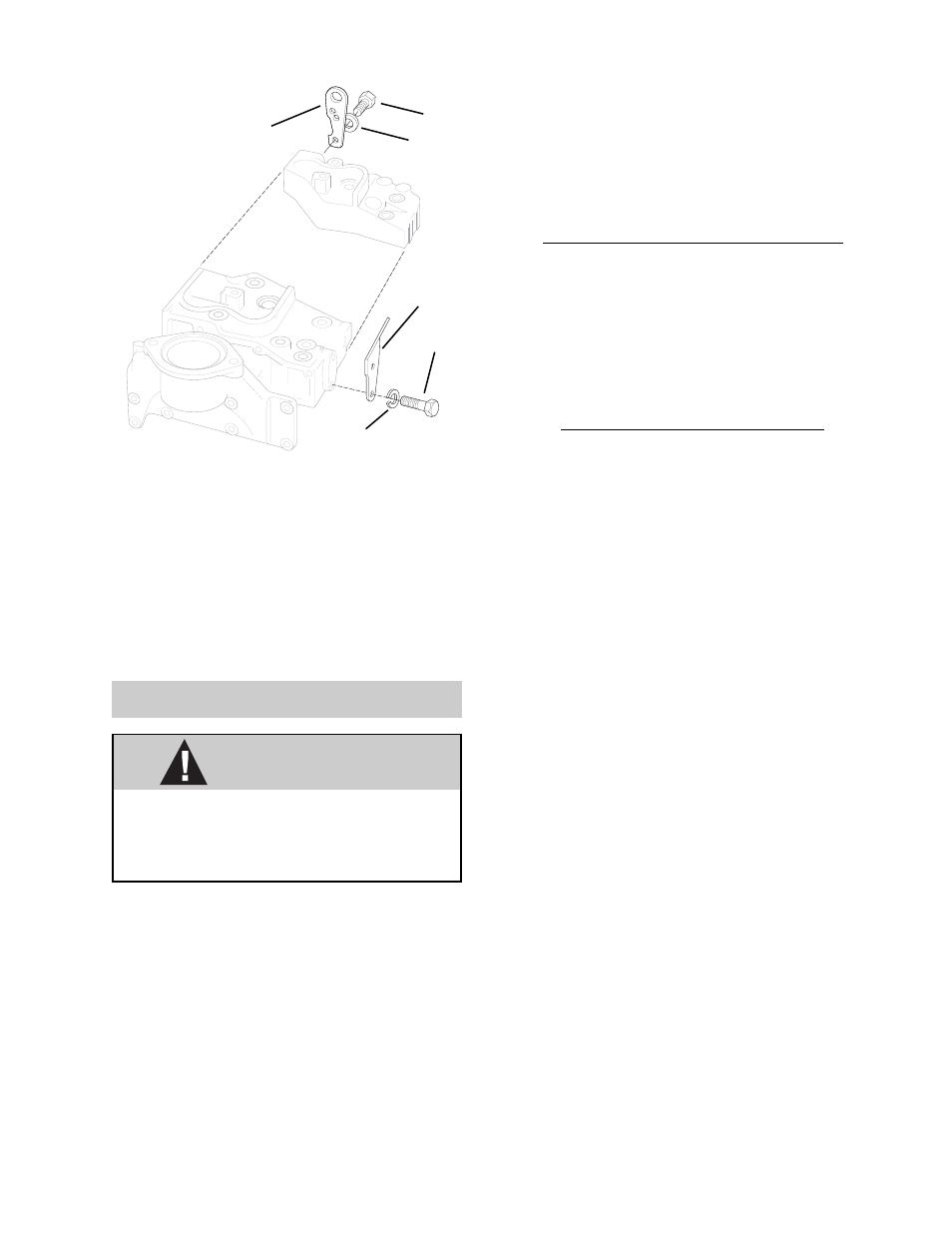
NOTE: Normally the engine and transmission are re-
moved as a unit by suspending both units from these
plates. The combined weight is 1,400 lb (635 kg).
Fig. 8.25 Engine Lifting Plates
5.
Washer (2)
6.
Plate
3.
Plate
4.
Screw (2)
1.
Screw (2)
2.
Washer (2)
MA0371