2 trigger operations, 1 trigger mode – BNC 1201 - 6 1/2 Digit Digital Multimeter User Manual
Page 69
70
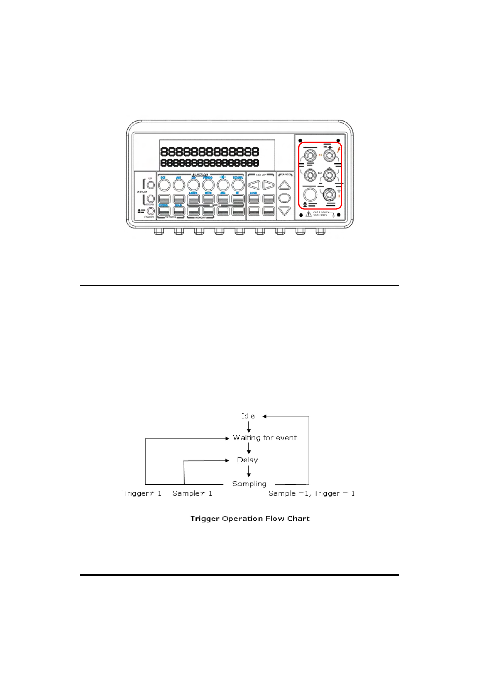
“TERMINALS” switch button on the front panel. Please see the following
figure for the location of the switch. The location of the button and
terminals is shown with a red rectangle frame in Figure 4-7.
Figure 4-7
4.2 Trigger Operations
In this section we will discuss the triggering system in 1201. 1201
provides a variety of trigger operations for user. User can select a trigger
mode, a trigger source and different trigger settings for a specific
measurement. The user’s selection is stored in a volatile memory and the
default settings will be restored after power-off. Figure 4-8 shows the
trigger operation in 1201.
Figure 4-8
4.2.1 Trigger Mode