Dynaflow, User manual - maintenance, Interface module dip sw1 settings – Ransburg DynaFlow User Manual User Manual
Page 84: Ransburg can bus address
LN-9400-00.9
80
DynaFlow
TM
User Manual - Maintenance
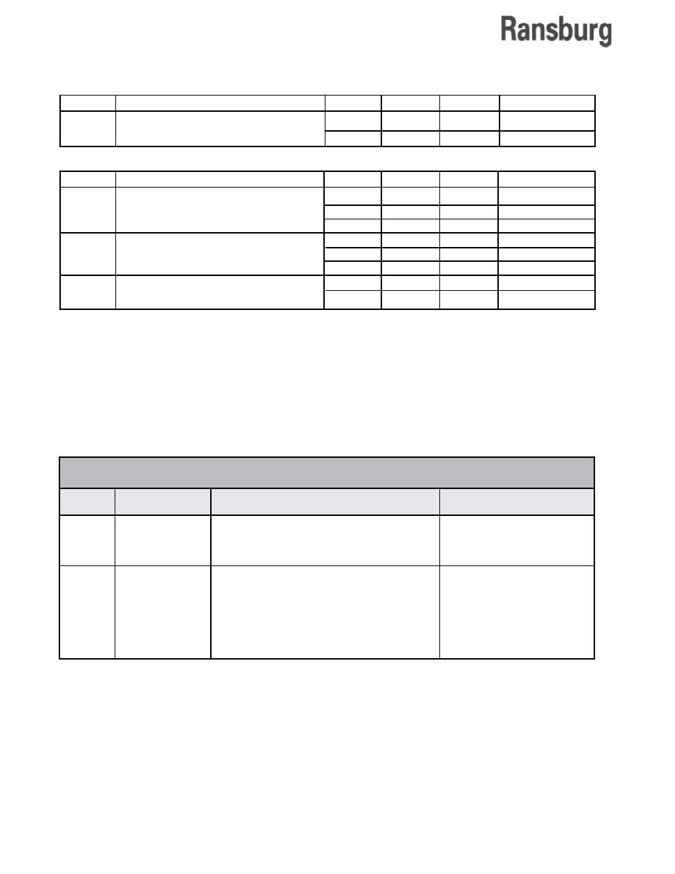
0 - 63 Decimal
0 - 77 Octal
0 - 3F Hex
Number of Channel
Cards:
1 to 4
1 to 4
1 to 3
1
Position
Description
Comments
1-6
7-8
RIO Rack address
position 1 = most significant bit (MSB)
position 6 = least significant bit (LSB)
RIO Starting Quarter position
7
8 Quarters
OFF OFF = 0
OFF ON
= 1/4
ON
OFF = 1/2
ON
ON
= 3/4
Default Setting
OFF
Address = 00
OFF
INTERFACE MODULE DIP SW1 SETTINGS
Jumper Description
JMP15 Flow Rate Freq. Input,
Channels A and B
Flowmeter Inputs:
FactorySetting
X
Type
Source
Sink
Pin 1-2
Open
Closed
Pin 2-3
Closed
Open
Jumper Description
JMP16
JMP17
JMP18
UVEPROM
RAM
Processor Pin EA
Memory and Processor Settings:
FactorySetting
X
X
X
Type
256KB
512 KB
1024 KB
8Kx8
16Kx8
32Kx8
Run
Prog.
Pin 1-2
Closed
Open
Open
Open
Closed
Closed
Open
Closed
Pin 2-3
Open
Closed
Closed
Closed
Open
Open
Closed
Open
Ransburg CAN Bus Address
Communication between the Interface Module
and Channel Cards.
The Control Area Network (CAN) address of the
Interface is automatically determined by hardware
based on the physical slot location in the rack.