Dynaflow, User manual - installation, Gun outputs – Ransburg DynaFlow User Manual User Manual
Page 27
LN-9400-00.9
DynaFlow
TM
User Manual - Installation
23
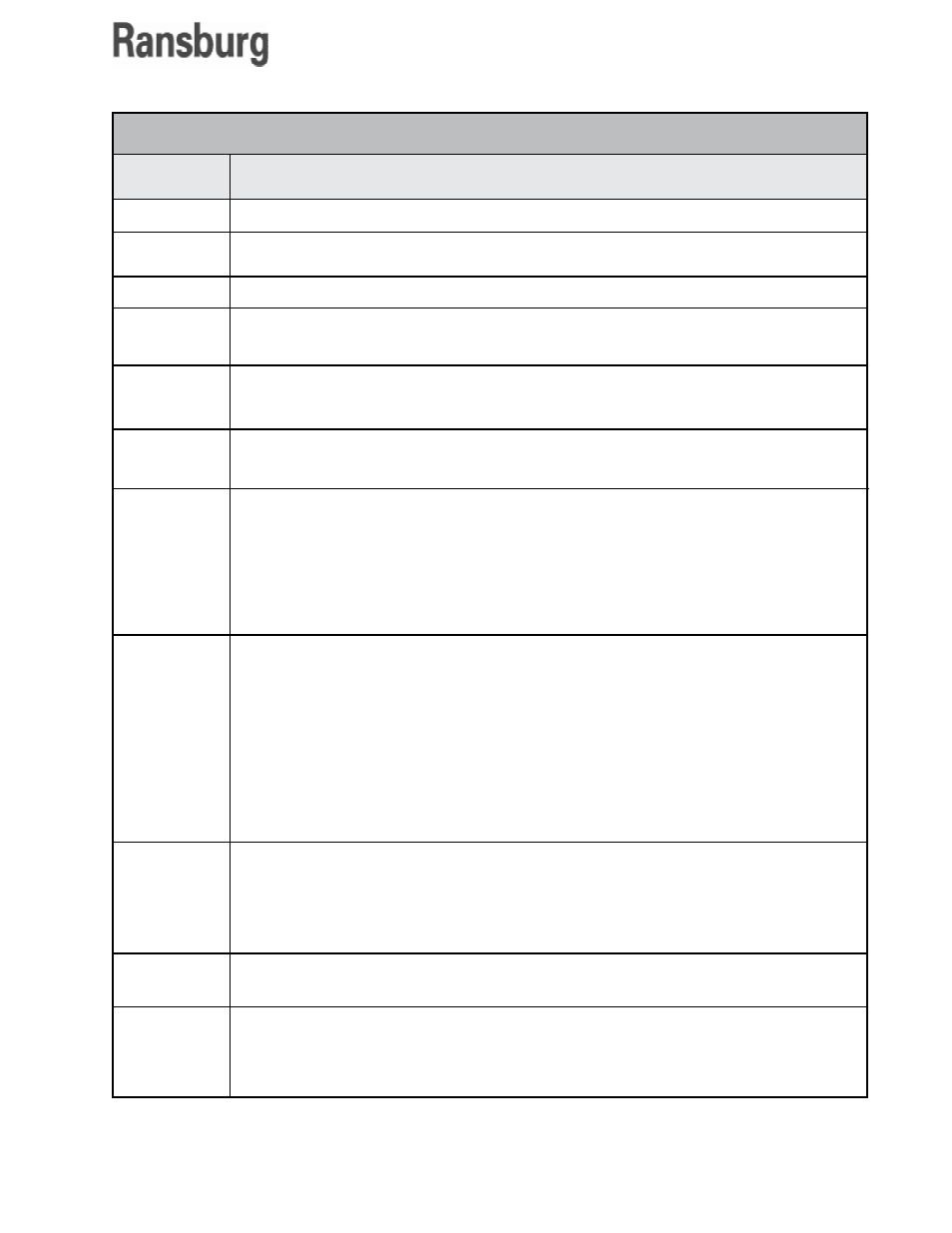
GUN OUTPUTS
Output
Signal
Description
Ready
Active
Fault
Pot Life Timer
Clean/Load/
Calibrate
MVR Enable
Analog Control
Output
Analog Flow
Rate Output
Fluid Line
Flushed Output
User Interface
Revision
Language
This output is 24 VDC when the GUN is configured properly, a valid JOB is loaded.
This output is 24 VDC when the GUN is RUN mode and flowing fluid or prepared to flow fluid.
This output is 24 VDC if a GUN fault condition occurs.
This output is 24 VDC if the Pot-Life Timer has expired. This may also initiate a horn if set to
do so in the Horn Code Configuration, set in the System Configuration.
This output is 24 VDC when the GUN is placed in Clean, Load, or Calibrate Mode.
This output is 24 VDC anytime material should be flowing for the GUN. It is used to control
trigger valve(s) installed at the inlet of the MVR valve(s) on fast-trigger JOBs.
This is a 0-10 VDC or 4-20 ma output signal (selectable on the Channel Module) which is
connected to the transducer for control of the material regulator for the CHANNEL. The
output signal is limited through the use of the JOB parameters, MVR HIGH and MVR LOW.
Scaling is assumed to be 0 VDC (4 ma) equals 0 PSIG at the output of the E/P transducer
and 10 VDC (20 ma) equals 100 PSIG at the output of the transducer. The MVR HIGH and
MVR LOW JOB parameters are based on a percentage of the span of 0 to 100 PSIG. This
an MVR LOW value of 10% equals 10 PSIG.
This is a 0-10 VDC or 4-20 ma output signal (selectable on the Channel Module) indicating
the actual flow rate for the CHANNEL. Scaling of the output signal is accomplished through
the use of the JOB parameters MAXIMUM FLOW RATE and MINIMUM FLOW RATE, where
0 VDC (4 ma) equals the MINIMUM FLOW RATE value and 10 VDC (20 ma) equals the
MAXIMUM FLOW RATE value.
For the Master Channel, if DIP switch 2/2 on the Interface Module is off, the total flow rate for
the gun is output and if the switch is on only the flow rate for the Master Channel is output.
For the Slave Channel, only the flow rate for the Slave Channel is output.
On guns configured for dual component operation, the pot-life expired output on the slave
(B) channel indicates when the fluid line has been completely flushed. Once mixed material
has entered the fluid line, this output is energized and it remains energized until the unit is
completely flushed. That is, in order to turn this bit off, the amount of material programmed
in for mixed volume must be expended from the applicator while the gun is in clean mode.
Displays the current version of the user-interface software running on the user-interface PC.
This allows users to select between English and one Alternate Language. The alternate
language text is stored on the flash drive or hard drive of the PC in files named: TEXT-
MESS_ALT.TXT, PARAMHLP_ALT.TXT, LABELS_ALT.TXT, SOLENOIDVALVES_ALT.TXT,
and HELP_ALT.TXT.