System components and parts identification, Dynaflow, User manual - maintenance – Ransburg DynaFlow User Manual User Manual
Page 76
LN-9400-00.9
72
DynaFlow
TM
User Manual - Maintenance
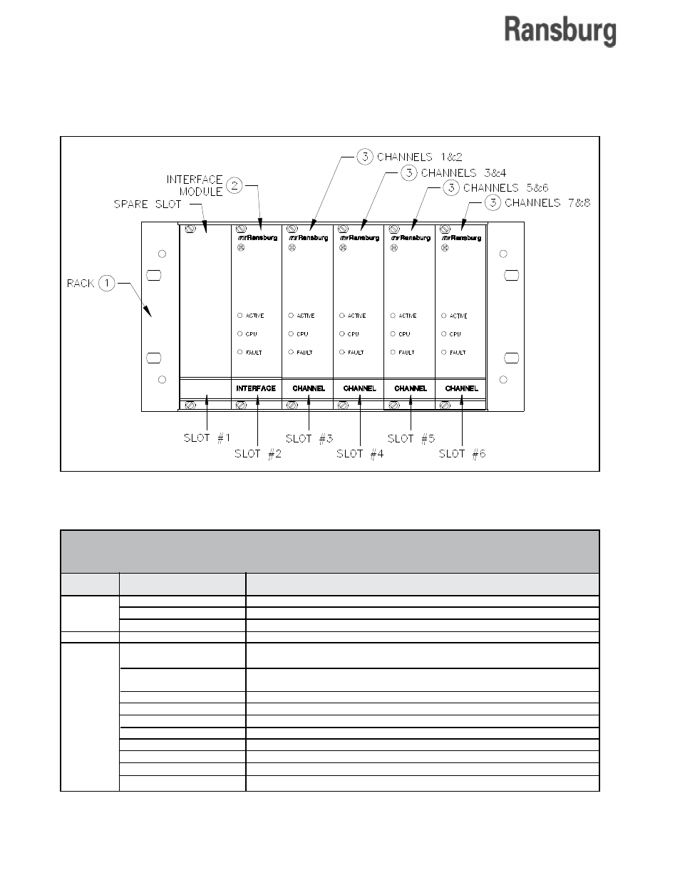
SYSTEM COMPONENTS AND PARTS IDENTIFICATION
Figure 7: Card Rack Assembly
1
77383-01
Rack Assembly, Empty, 1/2 Rack, 1 Mother Board
77383-02
Rack Assembly, Empty, Full Rack, 1 Mother Board
77383-03
Rack Assembly, Empty, Full Rack, 2 Mother Boards
2
77377-02
Interface Module Assembly, With RIO
3
A10946-01
Channel Module for use with 0-10VDC transducers and for the flow rate
indication output
A10946-02
Channel Module for use with 0-10VDC or 4-20mA transducers and for the
flow rate indication output
77378-00
Mother Board Assembly
LBAL0021-00
Interface Cable Assembly, Interface Panel to Control Panel, 40 ft.
LBAL5001-00
Interface Panel, Standard Two Component
LBAL5001-01
Interface Panel, GUN 1
LBAL5001-02
Interface Panel, GUN 2
A12182
Interface Panel W/Color Change
LPNE5002-00
Pneumatic Color Change Panel
LBAL5003-00
Pneumatic Operator Panel
Item #
DYNAFLOW SYSTEM COMPONENTS AND PARTS IDENTIFICATION
(Figure 7)
Part #
Description
Note: Refer to the "DynaFlow Operator Interface" manual for parts that are specific to the 77376
and A12233 Stand-Alone Control Panel.