Dynaflow, User manual - operation job select inputs, Job select inputs – Ransburg DynaFlow User Manual User Manual
Page 51
LN-9400-00.9
DynaFlow
TM
User Manual - Operation
JOB Select Inputs
These inputs are used to select a JOB number
from the external PLC or other host controller if
serial communication is not being used. These
inputs represent Binary Coded Decimal (BCD)
that translates to 3 digits, each digit represented
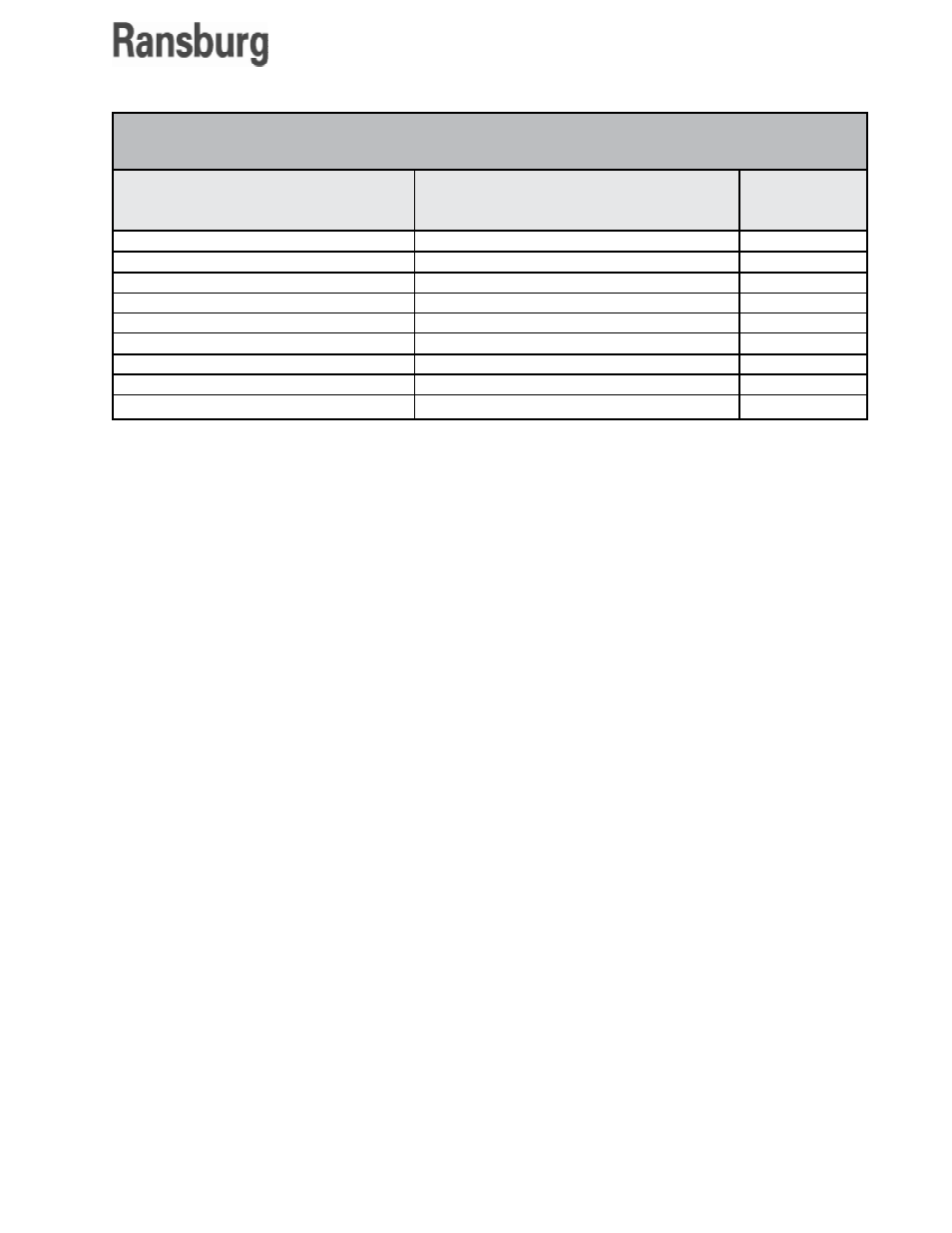
as a 4-bit binary code. The system inputs shown
in Figure 6 are used to select and enter a JOB
number. The JOB Select inputs are used in con-
junction with the GUN Mask inputs to determine
which GUNs will accept the JOB number repre-
sented by the total of the active JOB Select Bits.
Example: JOB #25 is Requested
Decimal Number = 25
Most Significant Digit (100's) = 0 = binary 0000
Most Significant Digit (10's) = 2 = binary 0010
Least Significant Digit (1's) = 5 = binary 0101
JOB numbers can be entered into the JOB Queue
at any time regardless of the operating mode.
These signals are used in conjunction with the
GUN MASK inputs to determine which GUN(S)
will receive the JOB # as input by the program
select inputs. The JOB SELECT inputs must be
present at the time that the JOB SELECT STROBE
signal is activated.
The basic sequence for selecting and entering
JOB numbers is:
1. Select and hold high the appropriate JOB
SELECT input bits.
2. Select and hold high the appropriate GUN
MASK input(s). This can be performed simutan-
eously with the JOB SELECT input bits.
3. Pulse the STROBE input.
4. Return all inputs to the low state (0 VDC).
Discrete System
Inputs
JOB Select #1
JOB Select #2
JOB Select #4
JOB Select #8
JOB Select #10
JOB Select #20
JOB Select #40
JOB Select #80
JOB Select #100
Selects BCD Bit #1
Selects BCD Bit #2
Selects BCD Bit #4
Selects BCD Bit #8
Selects BCD Bit #10
Selects BCD Bit #20
Selects BCD Bit #40
Selects BCD Bit #80
Selects BCD Bit #100
Toggles (enters) the
Selected Values
Value
1
2
4
8
10
20
40
80
100
JOB SELECT INPUTS
47