Pilot signal guidelines – Ransburg DynaFlow User Manual User Manual
Page 19
LN-9400-00.9
DynaFlow
TM
User Manual - Installation
15
Do not locate the Control Panel
near or adjacent to heat producing equip-
ment such as ovens, high wattage lamps,
steam pipes, etc.
C A U T I O N
!
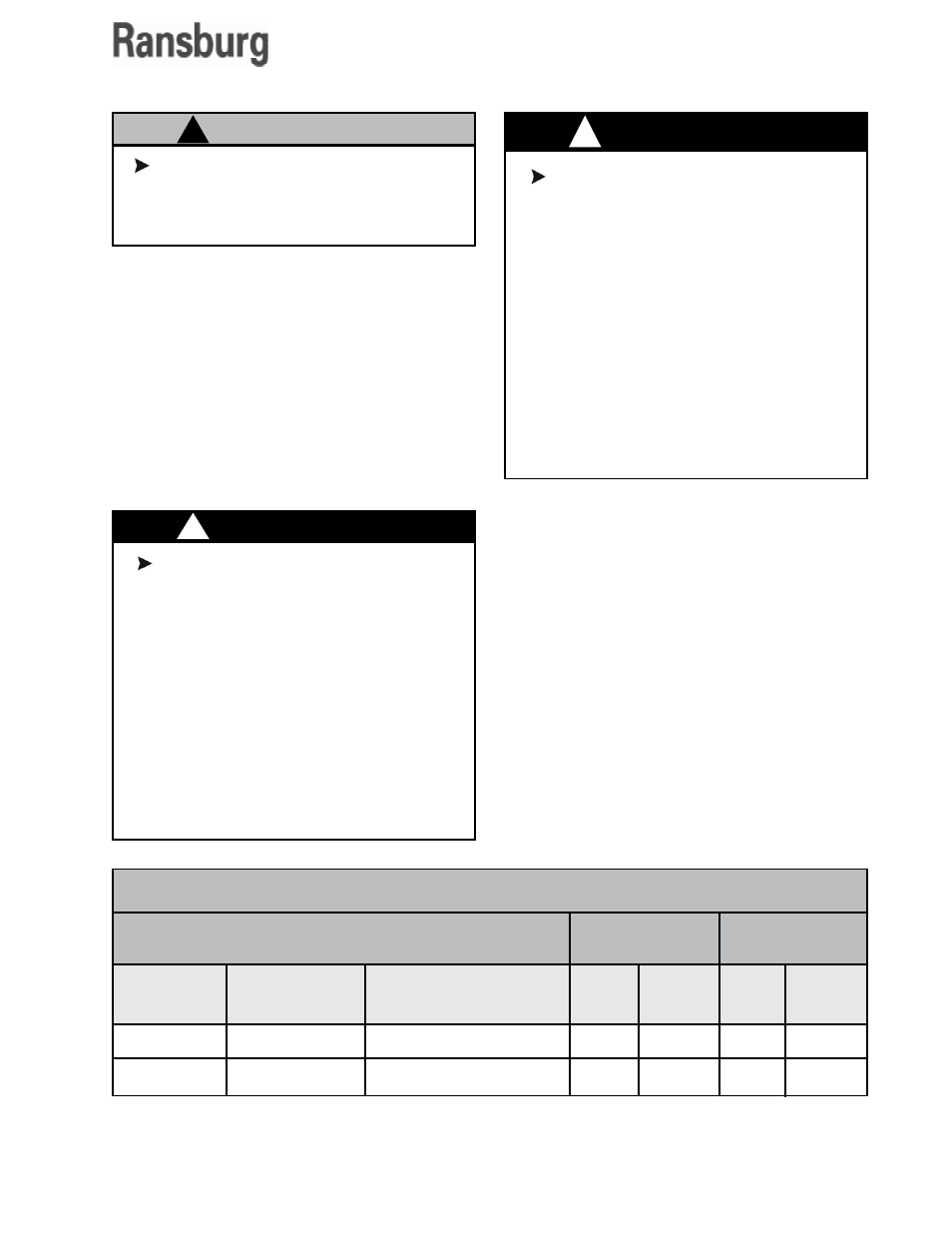
1/4"
1/4"
Tubing Size
OD
Fluid Regulator
Type
MVR
DR1
Typical
Application
Two-component
Single-Component
15
15
Feet
Meters
4.6
4.6
Feet
Meters
50
100
15.3
30.5
Maximum
Length
Minimum
Length
PILOT SIGNAL GUIDELINES
Equipment Mounting
Use the mounting ears supplied to mount the
control or interface enclosure on a wall or build-
ing structure. The anchor system used must be
rated to support the specified weight of the en-
closure being mounted (see specifications, page
13). When properly mounted, the anchor system
shall be capable of withstanding 4 times the rated
weight without causing a hazardous condition.
The Control Enclosure must be lo-
cated in such a way that access to the On/
Off power switch and Stop switch is not
blocked.
The On/Off switch turns off AC power to the
PC and 24 VDC supply.
The Stop switch interrupts only the 24
VDC.
The AC power input FUSED DISCONNECT
must be located in an accessible area near
the Control Enclosure
W A R N I N G
!
If improperly located, certain electrical
equipment can become a source of ignition
and create a risk of fire or explosion.
The Control and Interface Enclosures must
be located outside of the Class 1, Division
1 and 2 hazardous locations which are de-
fined for spray finishing of flammable and/
or combustible materials. Definitions and
requirements for classified areas are found
in the National Electrical Code, NFPA-70,
Article 516 and the National Fire Protection
Association (NFPA-33).
W A R N I N G
!