Specifying logical addresses -17, Specifying logical addresses – Rockwell Automation 1785-Lxxx Enhanced and Ethernet PLC-5 Programmable Controllers User Manual
Page 61
Publication 1785-UM012D-EN-P - July 2005
Addressing I/O and Controller Memory 4-17
Specifying Logical Addresses
The format of a logical address corresponds directly to the location in data
storage:
# X F : e . s / b
Where Is the
#
File address. Omit for bit, word, and structure addresses (also indicates indexed addressing, see next
page)
X
File type:B—binaryN—integerT—timerMG—message
C—counterO—outputA—ASCIIPD—PID
F—floating pointR—controlD—BCDSC—SFC status
I—inputS—statusBT—block-transfer ST—ASCII string
F
File number:0—output
1—input
2—status
3-999—any other type
:
colon or semicolon delimiter separates file and structure/word numbers
e
Structure/word number:0-277octal for input/output files
up to:0-127decimal for the status file
0-999for all the file types except MG, PD, and ST files
.
Period delimiter is used only with structure-member mnemonics in counter, timer and control files
s
Structure/member mnemonic is used only with timer, counter, control, BT, MG, PD, SC, and ST files
/
Bit delimiter separates bit number
b
Bit number:00-07 or 10-17 for input/output files
00-15 for all other files
00-15,999 for binary files when using direct bit address
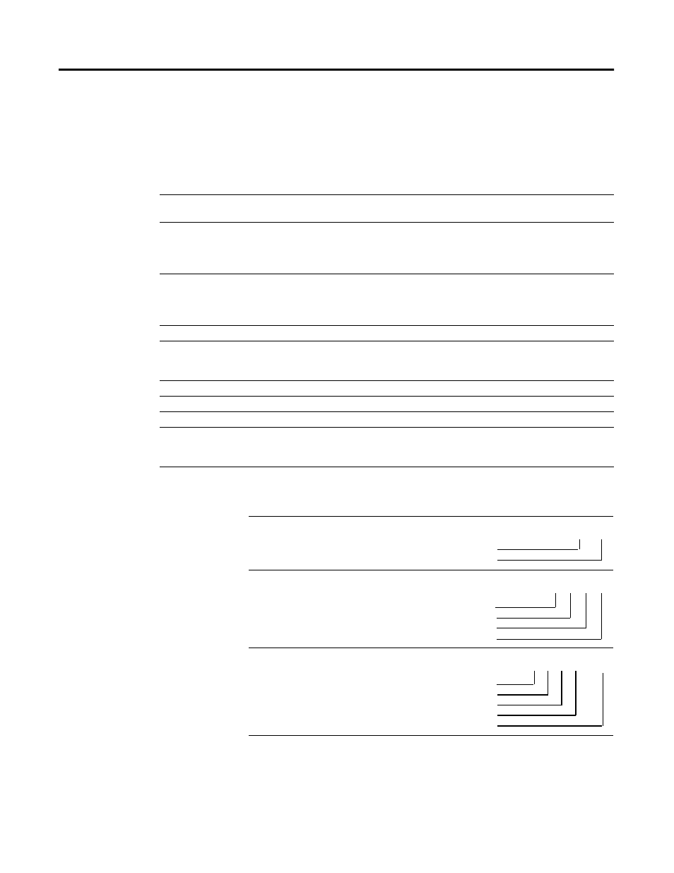
To Specify the Address of a Use these Parameters
File
Word within an integer file
Bit within an integer file
File Type
File Number
F
8
File Type
File Number
File Delimiter
Word Number
9
N
:
2
File Type
File Number
File Delimiter
Word Number
Bit Number
9
N
:
2 / 5