Rockwell Automation 1785-Lxxx Enhanced and Ethernet PLC-5 Programmable Controllers User Manual
Page 105
Publication 1785-UM012D-EN-P - July 2005
Communicating with a PLC-5 Adapter Channel 7-7
Discrete Data and Block-Transfer Status .
00
03
04
07
10
13
14
17
00
03
04
07
08
11
12
15
00
03
04
07
10
13
14
17
00
03
04
07
08
11
12
15
Word
0
1
2
3
4
5
6
7
Word
0
1
2
3
4
5
6
7
Supervisory Processor
PLC-2 0X0-0X7
PLC-3 OXX0-OXX7
PLC-5 O:X0-O:X7
Supervisory Processor
PLC-2 1X0-1X7
PLC-3 IXX0-IXX7
PLC-5 I:X0-I:X7
Output File
Input File
Input File
Output File
Reserved for status
Adapter Channel’s Input Destination File
Integer File
Adapter Channel’s Output Source File
Integer File
Reserved for status
Scanner’s Output Image Table
Scanner’s Input Image Table
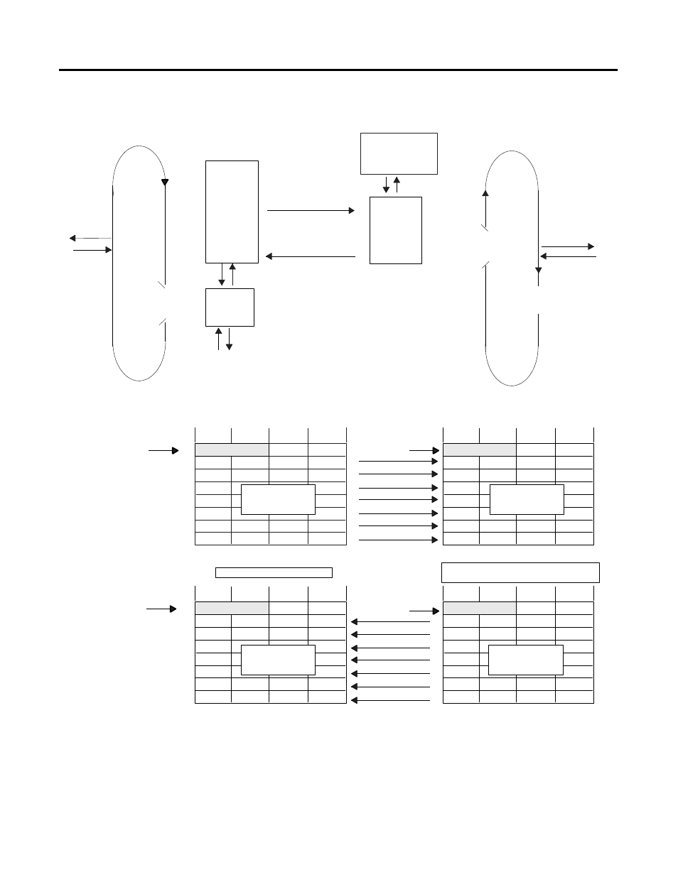
Two, four, six, or eight words of data can be transferred between the scanner and the adapter channel.
The number of words is determined by the rack size specified on the Adapter Channel Configuration screen.
Remote I/O Scan
Program Scan
Housekeeping
Buffer
Remote I/O
I/O Image
Table
Logic
Scan
Supervisory Processor in Scanner Mode
PLC-5 Processor Channel in Adapter Mode
Discrete Transfer
Configuration Files
Update
I/O image
Data Exchange
a
write outputs
b
read inputs
Housekeeping
Update
I/O image
a b
a
write
outputs
b
read
inputs
data from scanner’s
output image table sent
to the input source file
data from output source
file sent to scanner’s input
image table
Remote I/O
Buffer
Reserved for status
Reserved for status