Defining a controller input interrupt, Defining a controller input interrupt -5 – Rockwell Automation 1785-Lxxx Enhanced and Ethernet PLC-5 Programmable Controllers User Manual
Page 267
Publication 1785-UM012D-EN-P - July 2005
Using Processor Input Interrupts 18-5
Defining a Controller
Input Interrupt
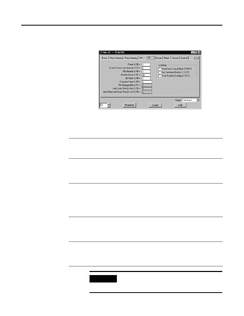
To define a PII, use the controller configuration screen in your programming
software.
In this PII
Configuration
Field
Do the Following
Status File
Address
Preset
Enter a preset value to determine how many conditions you want to
occur before the interrupt. Valid range is 0 - 32,767.
If you want the interrupt to occur every time, enter a 0 or 1.
S:50
File number
Enter the number of the program file that contains the
PII program.
This is the only PII parameter that you can change while the controller
is in RUN mode.
S:46
Module group
Enter the assigned rack number and I/O group number of the input to
monitor (e.g., 21 for rack 2, group 1). Do not enter the address. (Only
for inputs in the controller-resident chassis).
If the input word number specified is not in the local rack or if there is
not an input module in the slot addressed, a minor fault bit (S:10/11)
is set at mode transition.
S:47
Bit mask
Each module group (specified in S:47) has a control bit that is used to
monitor the input bit.
• To monitor the bit, enter a 1.
• To ignore the bit, enter a 0.
S:48
Compare value
Each module group (specified in S:47) has a bit that is used when
controlling a PII through bit transition.
• For a false to true transition to count (bit trigger), enter a 1.
• For a true to false transition to count (event trigger), enter a 0.
S:49
IMPORTANT
If you change the PII configuration while in run mode, you
must toggle the mode to program, then back to run mode
for the change to take effect.