Rockwell Automation 1785-Lxxx Enhanced and Ethernet PLC-5 Programmable Controllers User Manual
Page 116
Publication 1785-UM012D-EN-P - July 2005
7-18 Communicating with a PLC-5 Adapter Channel
Write ladder logic in the supervisory controller to monitor the rack-fault bits
for the rack that the adapter-mode controller channel is emulating to
determine the status of the remote I/O link.
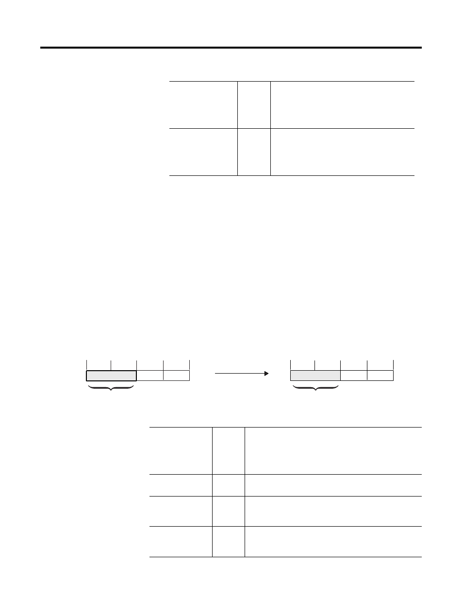
Monitoring the Status of the Supervisory Controller
The adapter-mode controller channel reserves bits 10-17 of the first word of
the input destination file for status. These bits tell the adapter-mode controller
channel the status of the supervisory controller and the integrity of the remote
I/O communication link.
When this Bit(s)
Is
It Indicates
10 octal (8 decimal)
and
15 octal (13 decimal)
0
adapter-mode controller is in run mode
10 octal (8 decimal)
and
15 octal (13 decimal)
1
adapter-mode controller is in program or test mode
When this Bit(s)
Is
It Indicates that the Adapter-Mode Controller
10 octal (8 decimal)
1
detects a communication failure or receives a reset command
from the supervisory controller
will be set if either bit 11 octal (9 decimal) or bit 15 octal (13
decimal) is set
11 octal (9 decimal)
1
receives a reset command from the supervisory controller
(controller in program or test mode)
13 octal (11 decimal) 1
detects that the supervisory controller has powered up; this bit
is reset with the first communication from the supervisory
controller
15 octal (13 decimal) 1
detects a communication failure (e.g., no communication
activity on the remote I/O communication link within the last
100 ms)
00
03
04
07
10
13
14
17
00
03
04
07
08
11
12
15
Word
0
Adapter Channel’s Input Destination File
Example Integer File
Scanner’s Output Image Table
Status of supervisory
processor
Not used by
adapter channel.