D-25 – Rockwell Automation 1785-Lxxx Enhanced and Ethernet PLC-5 Programmable Controllers User Manual
Page 325
Publication 1785-UM012D-EN-P - July 2005
Instruction Set Quick Reference D-25
Process Control, Message Instructions
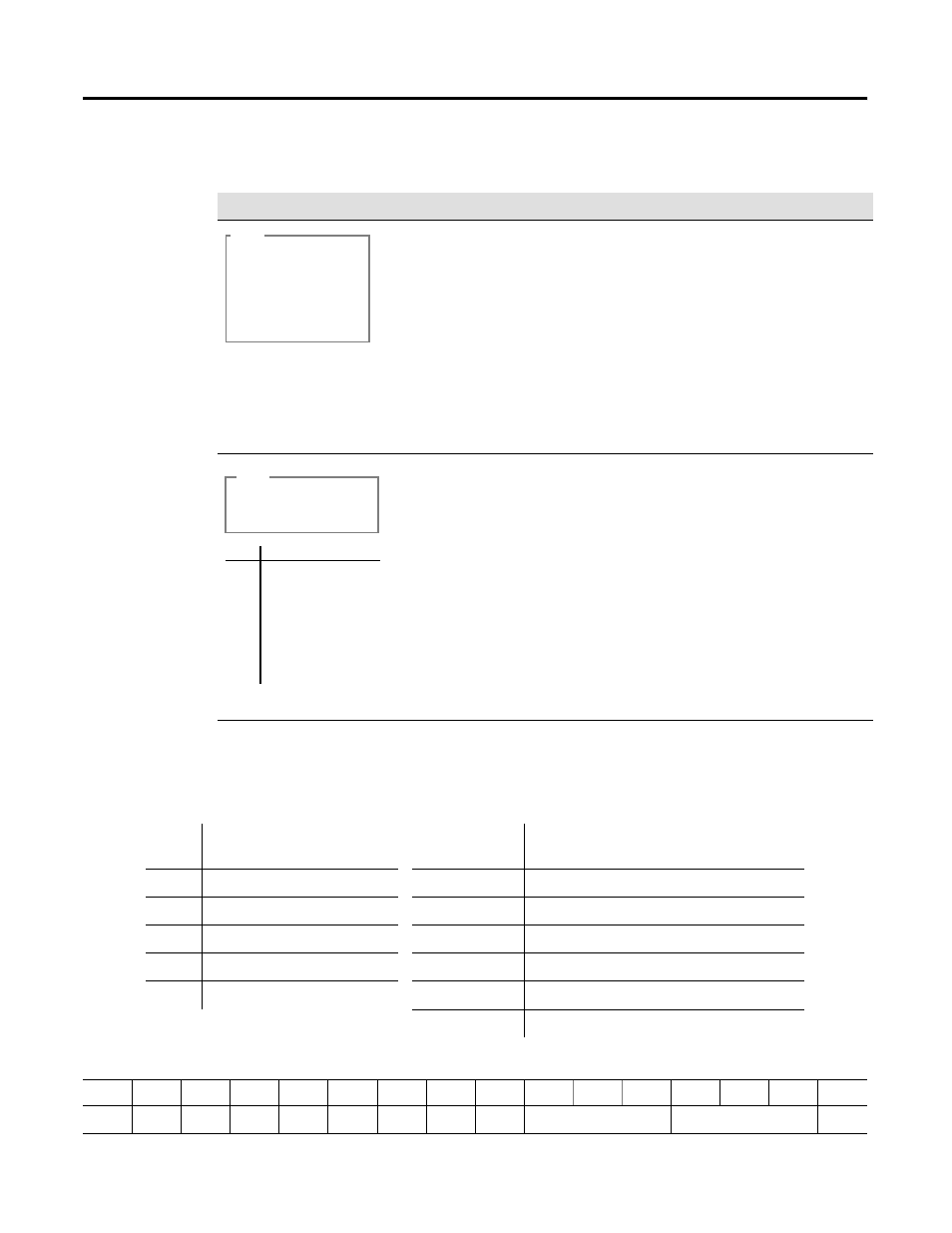
Block Transfer Instructions
Word 0
Instruction
Description
Proportional, Integral,
and Derivative
PID
Status Bits:
EN - Enable
DN - Done Bit
(for N
control blocks only)
The control block (PD10:0) contains the instruction information
for the PID. The PID gets the process variable from N15:13 and
sends the PID output to N20:21. The tieback stored in N15:14
handles the manual control station.
If you use an N control block, the rung must transition from
false to true for execution.
If you use PD control block, then there is no done bit. Also, the
rung input conditions need to be true.
See page F-8 for a description of prescan operation for
this instruction.
If the input conditions go from false to true, the data is
transferred according to the instruction parameters you set
when you entered the message instruction. The Control Block
(MG7:10) contains status and instruction parameters.
You can also use N control blocks.
For continuous MSGs, condition the rung to be true for only one
scan.
See page F-8 for a description of prescan operation for
this instruction.
PID
PID
PD10:0
Control Block
Proc Variable
Control Output
Tieback
N15:13
N20:21
N15:14
MSG
SEND/RECEIVE MESSAGE
Control Block
MG7:10
Bit #Status Bits
15EN - Enable
14ST - Start Bit
13DN - Done Bit
12ER - Error Bit
11CO - Continuous
10EW - Enabled-Waiting
9NR - No Response
Integer (N) control block
Block Transfer (BT) control block
Word
Offset
Description
Word
Mnemonic
Description
0
status bits (see below)
.EN through .RW
status bits
1
requested word count
.RLEN
requested length
2
transmitted word count
.DLEN
transmitted word length/error code
3
file number
.FILE
file number
4
element number
.ELEM
element number
.RGS
rack/group/slot
15
14
13
12
11
10
09
08
07
06
05
04
03
02
01
00
EN
ST
DN
ER
CO
EW
NR
TO
RW
** rack ** **
group** slot