Horner APG QX351 OCS HEQX351C103 User Manual
Page 26
CH.5
MAN0892-03-EN
February 25, 2010
Page 26 of 109
# 1039
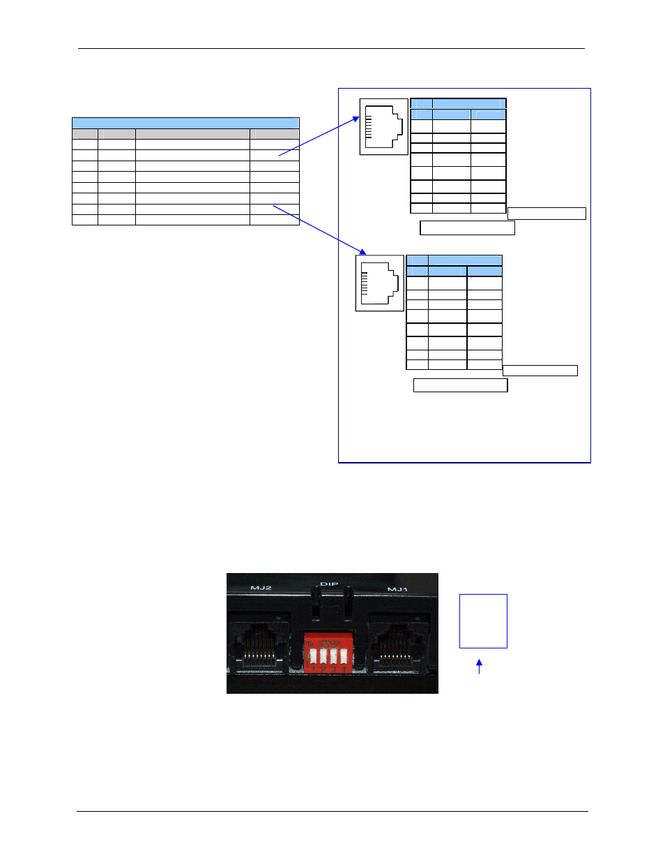
Figure 5.2: MJ Serial Port Connectors and DIP Switches for RS-485 Port Termination
Table 5.2 – – MJ2 Serial Port Pin Assignments
Pin
Signal
Signal Description
Direction
1
RX+
RS-485 Receive Positive
In
2
RX
−
RS-485 Receive Negative
In
3
TX+
RS-485 Transmit Positive
Out
4
TX
−
RS-485 Transmit Negative
Out
5
+5*
+5 VDC 60mA max
Out
6
0V
Ground
−
7
TD
1
RS-232 Transmit Data
In
8
RD
1
RS-232 Receive Data
Out
Switch
On
Position
MJ2 Pinouts in Full and Half Duplex Modes
* +5Vdc 60mA Max
Pin
MJ2 Pins
Signal
Direction
8
TXD
OUT
7
RXD
IN
6
0 V
Ground
5*
+5 60mA
OUT
4
TX-
OUT
3
TX+
OUT
2
RX-
IN
1
RX+
IN
1
8
MJ2 Full Duplex Mode
MJ2 Half Duplex Mode
Pin
MJ2 Pins
Signal
Direction
8
TXD
OUT
7
RXD
IN
6
0 V
Ground
5*
+5 60mA
OUT
4
TX-
OUT
3
TX+
OUT
2
TX-/RX-
IN/OUT
1
TX+/RX+
IN/OUT
1
8
* +5Vdc 60mA Max