Chapter 4: electrical installation – Horner APG QX351 OCS HEQX351C103 User Manual
Page 23
MAN0892-03-EN
CH.4
February 25, 2010 Page 23 of 109 #1039
CHAPTER 4: ELECTRICAL INSTALLATION
4.1
Initial Electrical Installation
Initially, it is important to refer to the data sheet sent with the product in the box.
The datasheet covers:
a.
Ports and Connectors
b.
Wiring and Pin-outs
Visit our website (
http://www.heapg.com/
) to obtain updates to datasheets and user documentation.
4.2
Grounding Definition
Ground: The term Ground is defined as a conductive connection between a circuit or piece of
equipment and the earth. Grounds are fundamentally used to protect an application from harmful
interference causing either physical damage such as by lightning or voltage transients or from circuit
disruption often caused by radio frequency (RF) interference.
4.3
Ground Specifications
Ideally, a ground resistance measurement from equipment to earth ground is 0 ohms. In reality it typically
is higher. The U.S. National Electrical Code (NEC) states the resistance to ground shall not exceed 25
ohms. Horner APG recommends less than 15 ohms resistance from our equipment to ground.
Resistance greater than 25 ohms can cause undesirable or harmful interference to the device.
4.4
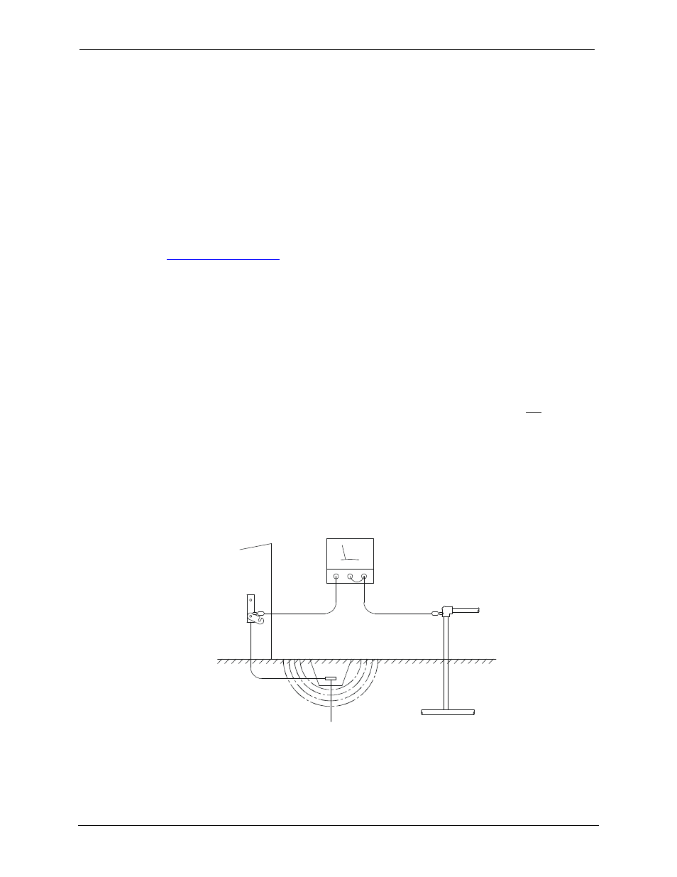
How to Test for Good Ground
In order to test ground resistance, a Ground Resistance Tester must be used. A typical Ground
Resistance Meter Kit contains a meter, two or three wire leads, and two ground rods. Instructions are
supplied for either a two-point or three-point ground test. Figure 4.1 shows a two-point ground
connection test.
Figure 4.1: Two-Point Ground Connection Test
METAL WATER PIPE OR
OTHER GOOD GROUND
GROUND ROD
GROUND
DISCONNECTED
FROM SERVICE
GROUND RESISTANCE METER