Shared uplink sets (associated networks) screen – HP Virtual Connect 4Gb Fibre Channel Module for c-Class BladeSystem User Manual
Page 137
Virtual Connect networks 137
2.
Create new network names for the associated networks (VLANs). To be renamed, all networks must
share a common part of the naming convention. For example, if the original network names end in –A,
you can replace that portion of the name with –B for the copied networks.
a.
Select an option in the Replace pull-down menu:
—
all—Replaces all instances of the search string with the replacement string
—
first—Replaces the first instance of the search string with the replacement string
—
last—Replaces the last instance of the search string with the replacement string
b.
Enter the search string in the first text box.
c.
Enter the replacement string in the second text box.
d.
Compare the side-by-side scrolling lists of associated networks to be sure that each network is
renamed properly.
Notes:
o
The search string and the replacement string can be different lengths.
o
The search string must be found in all associated network names.
o
The replacement string can be empty.
o
The new associated network names cannot be duplicates of existing network names, and the names
must follow the normal network name rules.
o
You cannot edit the associated network names individually on this screen. After the associated
networks are created, you can rename the networks as normal.
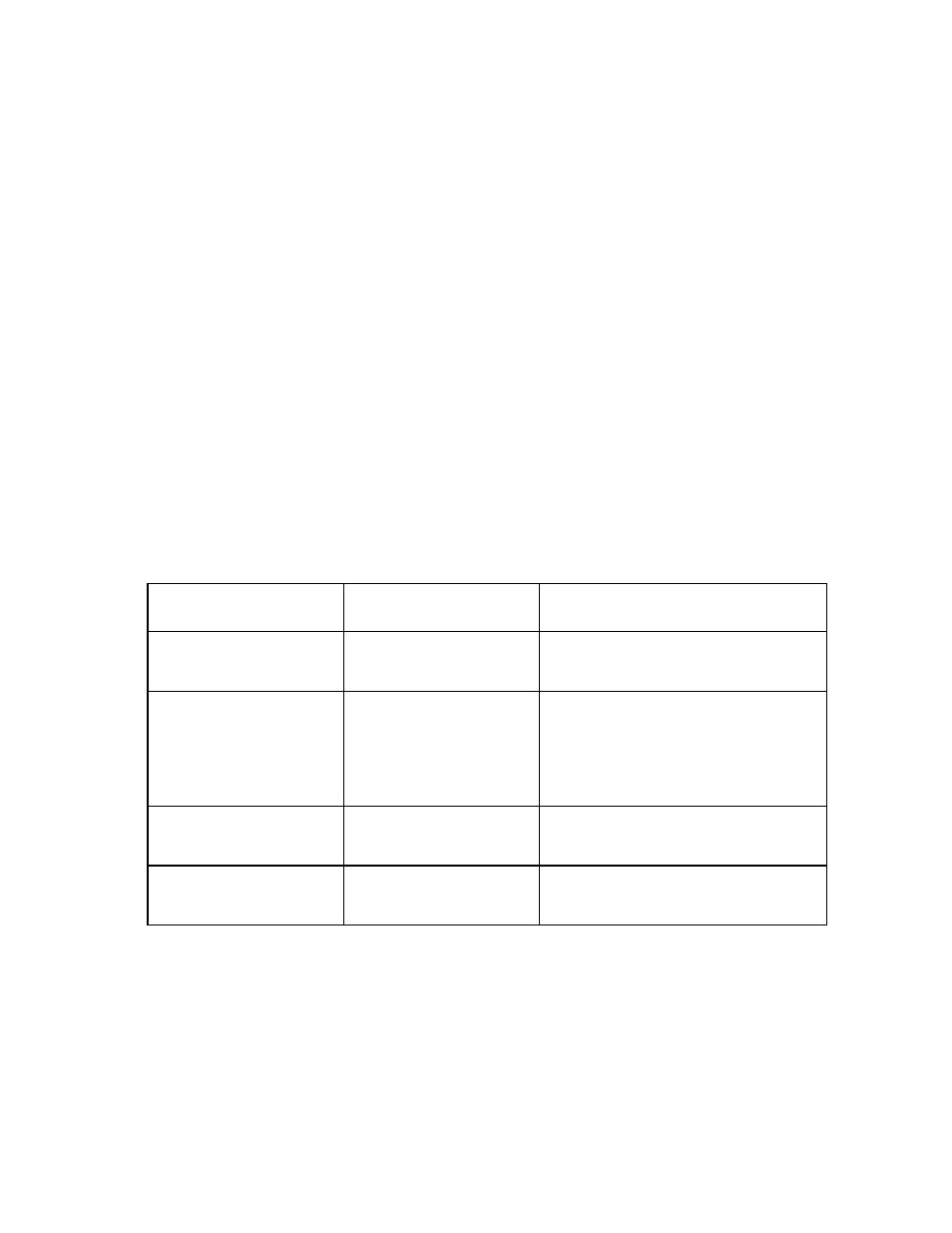
Examples:
Associated network name
before
Associated network name
after
Replacement scheme
vendorSUS-vlan-1-A
vendorSUS-vlan-2-A
vendorSUS-vlan-3-A
vendorSUS-vlan-1-B
vendorSUS-vlan-2-B
vendorSUS-vlan-3-B
Replace last instance(s) of –A with –B
BANK_SUS_A-10
BANK_SUS_A-11
BANK_SUS_A-12
BANK_SUS_B-10
BANK_SUS_B-11
BANK_SUS_B-12
Replace last instance(s) of A with B
Note: If you select all, the A in BANK would be
replaced with a B, resulting in
BBNK_SUS_B-10. Similarly, if you select first,
only the A in BANK would be replaced with a
B, resulting in BBNK_SUS_A-10.
SUS-BAY1-vlan100
SUS-BAY1-vlan101
SUS-BAY1-vlan102
SUS-BAY2-vlan100
SUS-BAY2-vlan101
SUS-BAY2-vlan102
Replace first instance(s) of BAY1 with BAY2
-or-
Replace first instance(s) of 1 with 2.
Test-Net-300
Test-Net-310
Test-Net-320
Production-Net-300
Production-Net-310
Production-Net-320
Replace first instance(s) of Test with Production
3.
Select the external uplink ports for the new shared uplink set.
4.
Click OK to create the new shared uplink set and associated networks.
Shared Uplink Sets (Associated Networks) screen
To access this screen, click the Shared Uplink Sets link in the left navigation tree, and then click the Associated
Networks tab.