3 cable layout and shielding (emc measures), Cable layout and shielding (emc measures), Fig. 7: installation and cable laying information – NORD Drivesystems BU0060 User Manual
Page 38: Notice, Potential equalisation
CANopen – Supplementary manual options for NORD - Frequency Inverters
38
BU 0060 GB-4112
3.3 Cable layout and shielding (EMC measures)
If EMC measures are not in place, high-frequency interference which is mainly caused by switching
processes or lightning often causes electronic components in the bus subscribers to be faulty and
error-free operation can no longer be ensured.
Appropriate shielding of the bus cable reduces electrical interference which can arise in an industrial
environment.
The best shielding qualities can be achieved with the following measures:
• Do not make cable connections shorter than 1 m between bus participants
• Avoid long connections between bus participants
• Shield the bus cable at both ends with large-area connection to the plug housing
• Avoid spur lines
• Avoid extensions to bus cables via plug connectors
Bus lines should be laid with a minimum spacing of 20 cm to other lines which carry a voltage higher
than 60 V. This applies to lines laid inside and outside of control cabinets.
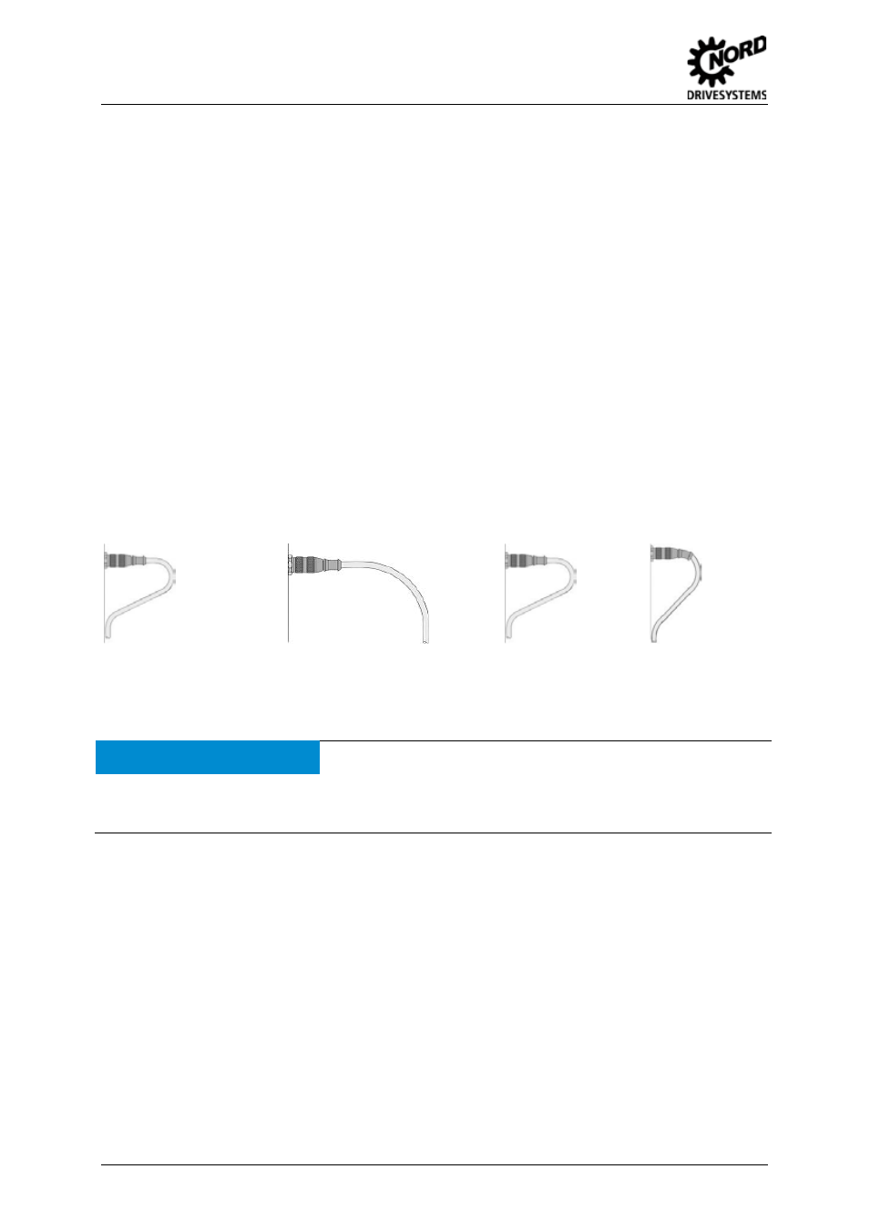
Special attention should be paid to bending radii:
Fixed cable
Freely laid cable
Bending radius of cable
Minimum radius
5 x cable diameter
Minimum radius
10 x cable diameter
Correct
Incorrect
Fig. 7: Installation and cable laying information
NOTICE
Potential equalisation
If earthing potential values are different, transient current may flow through shielding which is connected on both
sides. This may be a danger to electronic components. Differences in potential must be reduced by means of
adequate potential equalisation.
Pos : 59 /Anl eitungen/ Elektroni k/ Bus s yst eme/4. Kommuni kati on und Prot okoll + Proz ess datentr ans fer /! Kapitel Kommuni kation und Pr ot okoll @ 1\ mod_1342081745953_388. doc x @ 31856 @ 1 @ 1