4 canopen module, sk tu3-cao, Canopen module, sk tu3-cao, Information – NORD Drivesystems BU0060 User Manual
Page 20: Rotary coding switches
CANopen – Supplementary manual options for NORD - Frequency Inverters
20
BU 0060 GB-4112
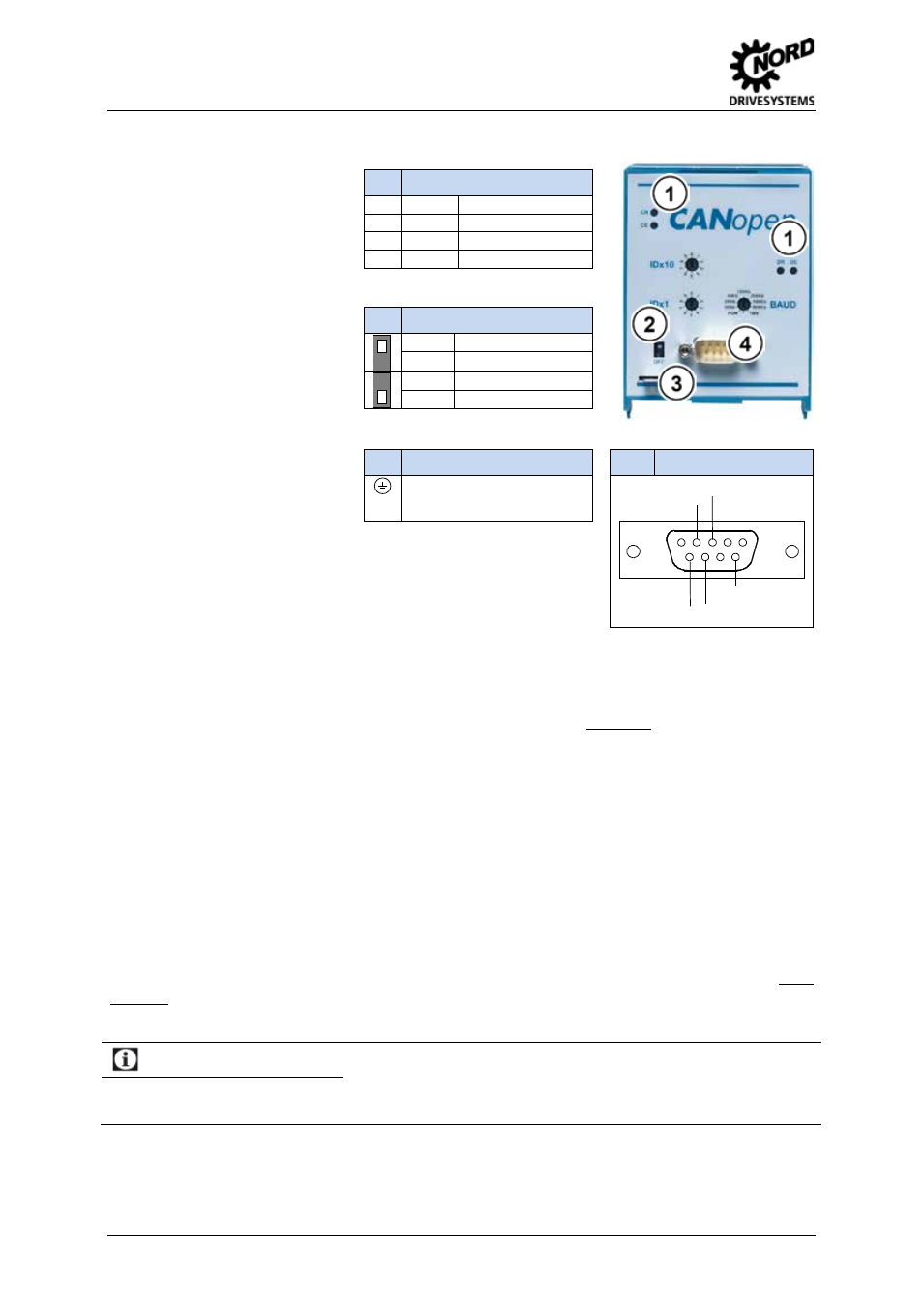
2.1.4 CANopen module, SK TU3-CAO
This CANopen module can be
used for all SK 500E devices. It
occupies the technology slot
which can then no longer be used
for control and display modules.
Alternatively, the SimpleBox SK
CSX-0 can be plugged in to the
CANopen module and connected
to the frequency inverter via the
RS232/485 interface.
The CANopen module must be
provided with a 24 V external
power supply (via SUB – D9
connection). This CAN participant
can therefore be identified by the
master system even without a
voltage supply to the frequency
inverter. The data required for this
purpose are set using a rotary
coding switch. This Bus data is
read in when the 24V is applied
from the frequency inverter.
1
CANopen Status LEDs
CR
(green)
CANopen RUN
CE
(red)
CANopen ERROR
DR
(green)
Module status
GB
(red)
Module error
2
Termination resistor
(ON)
Connected
(OFF)
Not connected
3
Shielding terminal
Connection to PE of the
frequency inverter to suppress
interference in the Bus lines
4
SUB – D9
GND
CAN_L
6
1
5
9
GND
CAN_H
24V in
Baud rate (BAUD)
Transfer rates of up to 500 kbit/s can be used (optionally up to 1Mbit/s).
If BAUD is set to PGM the value from parameter P514 is used as the baud rate.
Supply voltage
The supply voltage is 24 V DC ±25% (Pin 9 = 24 V, Pin 3 = GND, approx. 80 mA). The connection is
made via the SUB-D9 connector.
Termination resistor
The termination resistor for the last Bus participant is located on the CANopen Bus module.
CAN address, setting the ID (IDx1 and ID10)
The rotary switches IDx1 and IDx10 can be used to set the node identifier in decimal code in the
range from 01...99
dez
.
Example: Node ID = 64
à
IDx10 = 6, IDx1 = 4
If BAUD is set to PGM the value from parameter P515 of the frequency inverter is used as the node
identifier.
Information
Rotary coding switches
The settings made using the rotary coding switch are not transferred to the frequency inverter or saved. Changed
settings are only adopted when the 24V supply is applied ("Power ON").
Pos : 37 /Anl eitungen/ 3. Anzeig e und Bedienung [SK 500E]/ SK 5xxE/ 3. 2 Ü bersicht der T ec hnologi eboxen -2- M ontag e @ 1\ mod_1340712929975_388.doc x @ 28340 @ 3 @ 1