2 canopen module, sk tu2-cao, Canopen module, sk tu2-cao, Information – NORD Drivesystems BU0060 User Manual
Page 32: Rotary coding switches
CANopen – Supplementary manual options for NORD - Frequency Inverters
32
BU 0060 GB-4112
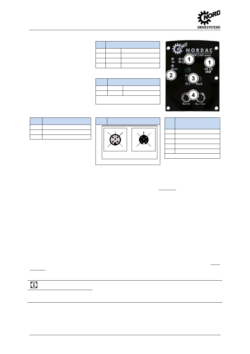
2.3.2 CANopen module, SK TU2-CAO
The CANopen module must be
provided with a 24 V external
power supply (via SUB - D9
connection). This CAN
participant can therefore be
identified by the master system
even without a voltage supply to
the frequency inverter. The data
required for this purpose are set
using a rotary coding switch.
This Bus data is read in when
the 24 V is applied from the
frequency inverter.
1
CANopen Status LEDs
CR
(green)
CANopen RUN
CE
(red)
CANopen ERROR
DR
(green)
Module status
GB
(red)
Module error
2
SK 300E status LEDs
On
(green)
Mains voltage applied
Error
(red)
Inverter error*
* The flashing frequency corresponds to
the error number (see BU0300)
3
Rotary coding switches
ID-H
Addressing ( ID x 10 )
ID-L
Addressing ( ID x 1 )
Baud
Baud rate
4
M12 BUS-In / BUS-Out
4
Plug connector
assignment:
1
PE (shield) *
2
+24V
3
GND
4
CAN-H
5
CAN-L
* Pin 1 and housing
Baud rate (BAUD)
Transfer rates of up to 500 kbit/s can be used (optionally up to 1Mbit/s).
If BAUD is set to PGM the value from parameter P514 is used as the baud rate.
Supply voltage
The supply voltage is 24 V DC ±25% (Pin 9 = 24 V, Pin 3 = GND, approx. 80 mA). The connection is
made via the SUB-D9 connector.
Termination resistor
The termination resistor for the last bus participant can be switched to the output (BUS-Out) of the
final frequency inverter as the termination connector.
CAN address, setting the ID (ID-L and ID-H)
The rotary switches ID-L and ID-H can be used to set the node identifier in decimal code in the range
from 01...99
dez
.
Example: Node ID = 64
à
ID-H = 6, ID-L = 4
If BAUD is set to PGM the value from parameter P515 of the frequency inverter is used as the node
identifier.
Information
Rotary coding switches
The settings made using the rotary coding switch are not transferred to the frequency inverter or saved. Changed
settings are only adopted when the 24V supply is applied ("Power ON").
Pos : 51 /Anl eitungen/ Elektroni k/ Bus s yst eme/2. Baugruppen/Mont age der SK TU 2-T echnologiebox @ 1\ mod_1335440910321_388.doc x @ 22864 @ 35 @ 1
Stift
(Bus-In)
Buchse
(Bus-Out)
(aus Bauteilesicht, A-kodiert)
2
1
4
3
5
1
2
3
5
4