Bus configuration, 1 laying the bus cables, 2 cable material – NORD Drivesystems BU0060 User Manual
Page 37: Laying the bus cables, Cable material, Table 6: transfer speeds versus cable length, 3 bus configuration
3 Bus Configuration
BU 0060 GB-4112
37
3. Bus Configuration
A CAN network consists of a maximum of 128 participants (nodes) and is based on a linear topology.
The number of subscribers is dependent on the driver modules (standard approx. 100 nodes).
Repeaters must be used for a high number of nodes.
With NORD frequency inverters, a twisted two-wire line is used for data transfer.
Pos : 56 /Anl eitungen/ Elektroni k/ Bus s yst eme/3. Bus auf bau/C AN open [ BU0060] /Verleg ung der Bus kabel @ 1\ mod_1342078992314_388.doc x @ 31779 @ 2 @ 1
3.1 Laying the bus cables
In an industrial environment the correct installation of the bus system is particularly important in order
to reduce potential interference. The following points are designed to help prevent interference and
problems right from the start. The installation guidelines are not complete and applicable safety and
accident prevention guidelines must be complied with.
Pos : 57 /Anl eitungen/ Elektroni k/ Bus s yst eme/3. Bus auf bau/C AN open [ BU0060] /Leit ungs mat erial @ 1\ mod_1342079075458_388. doc x @ 31804 @ 2 @ 1
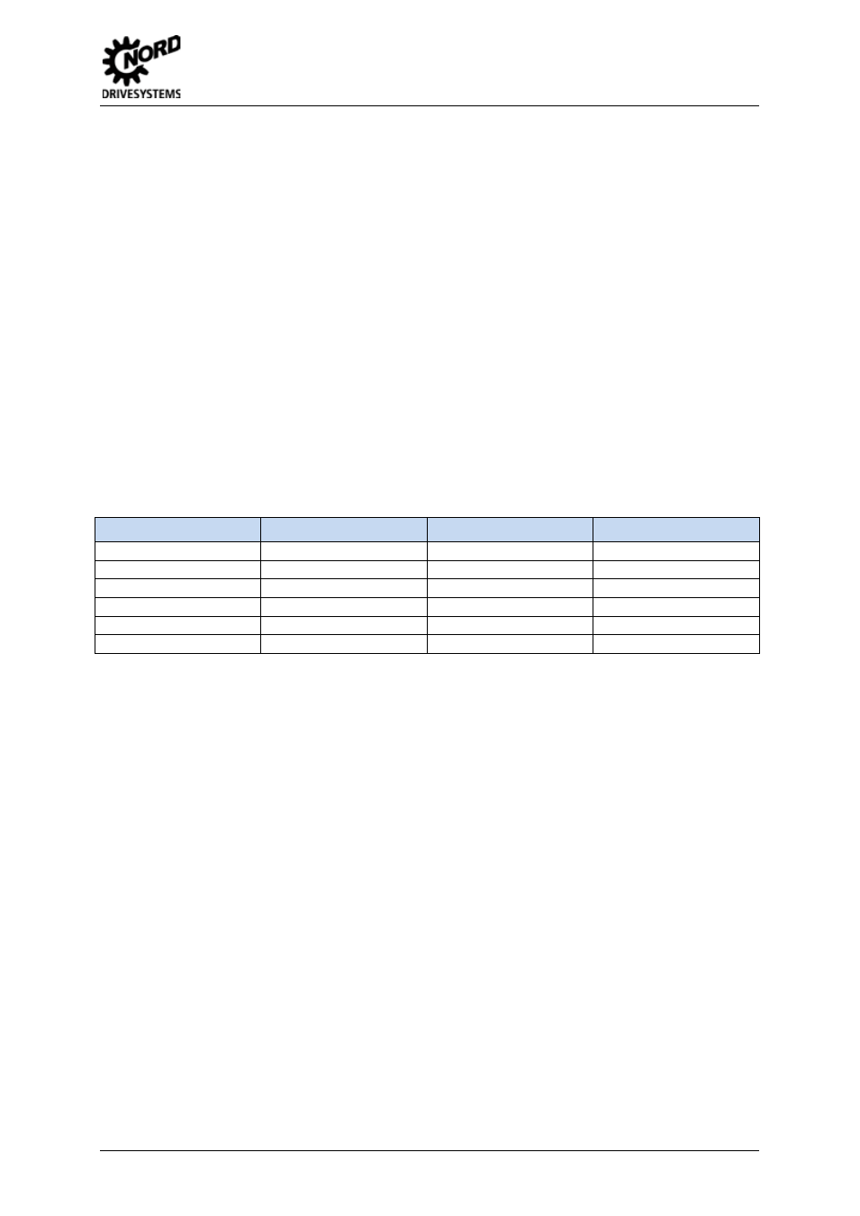
3.2 Cable material
The frequency inverter is usually connected to the CANnord system by a twisted, shielded two-wire
cable. The guaranteed transfer speeds or transfer distances can only be achieved without errors if the
specific cable parameters are complied with.
Bus cable length
Resistance
Cable cross-section
Possible transfer rates
Up to 25m
70 mΩ/m
≥ 0.25 mm2, AWG23
1 Mbit/s
25 - 50m
70 mΩ/m
≥ 0.25 mm2, AWG23
800 kBits/s
50 - 80m
< 60 mΩ/m
≥ 0.34 mm2, AWG22
500 kBits/s
80m - 230m
< 40 mΩ/m
≥ 0.5 mm2, AWG21
250 kBits/s
230m – 480m
< 26 mΩ/m
≥ 0.75 mm2, AWG18
125 kBits/s
480m – 1km
< 20 mΩ/m
≥ 1 mm2, AWG…
50 kBits/s
Table 6: Transfer speeds versus cable length
The interface complies with ISO 11898. The maximum permissible voltage on the CAN_L and CAN_H
cables is -8V … +8V.
Pos : 58 /Anl eitungen/ Elektroni k/ Bus s yst eme/3. Bus auf bau/ Leitungsf ühr ung und Sc hir mung (EM V- Maß nahmen) @ 1\ mod_1335520188525_388. doc x @ 24384 @ 2 @ 1