Electrical connections – KROHNE OPTISONIC 3400 EN User Manual
Page 45
ELECTRICAL CONNECTIONS
4
45
OPTISONIC 3400
www.krohne.com
11/2013 - 4002037702 - HB OPTISONIC 3400 -en-R02
Pulse/frequency output active, modular I/Os
• U
nom
= 24 VDC
• f
max
in the operating menu set to f
max
≤ 100 Hz:
I ≤ 20 mA
open:
I ≤ 0.05 mA
closed:
U
0, nom
= 24 V at I = 20 mA
• f
max
in operating menu set to 100 Hz < f
max
≤ 10 kHz:
I ≤ 20 mA
open:
I ≤ 0.05 mA
closed:
U
0, nom
= 22.5 V at I = 1 mA
U
0, nom
= 21.5 V at I = 10 mA
U
0, nom
= 19 V at I = 20 mA
• If the following maximum load impedance R
L, max
is exceeded, the load impedance R
L
must
be reduced accordingly by parallel connection of R:
f ≤ 100 Hz: R
L, max
= 47 kΩ
f ≤ 1 kHz: R
L, max
= 10 kΩ
f ≤ 10 kHz: R
L, max
= 1 kΩ
• The minimum load impedance R
L, min
is calculated as follows:
R
L, min
= (U
ext
- U
0
) / I
max
• X designates the connection terminals A, B or D, depending on the version of the signal
converter.
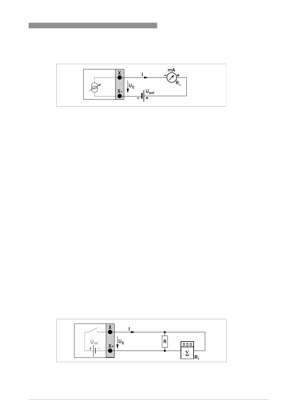
Figure 4-13: Current output passive I
p
Figure 4-14: Pulse / frequency output active P
a
- BATCHFLUX 5500 C Quickstart EN (20 pages)
- IFC 050 Converter Quickstart EN (28 pages)
- IFC 100 Converter Quickstart EN (32 pages)
- IFC 300 Converter Quickstart EN (68 pages)
- OPTIFLUX 1000 Quickstart EN (20 pages)
- OPTIFLUX 2000 Quickstart EN (24 pages)
- OPTIFLUX 4000 Quickstart EN (24 pages)
- OPTIFLUX 4040C Quickstart EN (16 pages)
- OPTIFLUX 5000 Flange Quickstart EN (20 pages)
- OPTIFLUX 5000 Sandwich Quickstart EN (20 pages)
- OPTIFLUX 6000 Quickstart EN (28 pages)
- OPTIFLUX 7300 Quickstart EN (24 pages)
- OPTIPROBE Quickstart EN (16 pages)
- TIDALFLUX 2300 F EN (44 pages)
- TIDALFLUX 2300 F Quickstart EN (24 pages)
- WATERFLUX 3000 EN (40 pages)
- WATERFLUX 3000 Quickstart EN (24 pages)
- WATERFLUX 3070 EN (80 pages)
- WATERFLUX 3070 Quickstart EN (32 pages)
- USB ADAPTER PLUS EMF EN (16 pages)
- IFC 050 Converter Modbus EN (20 pages)
- IFC 100 Converter FOUNDATION FIELDBUS EN (64 pages)
- IFC 100 Converter Modbus EN (20 pages)
- IFC 300 Converter FOUNDATION FIELDBUS EN (60 pages)
- IFC 300 Converter HART 0102 EN (20 pages)
- IFC 300 Converter HART 0201 EN (23 pages)
- IFC 300 Converter Modbus EN (24 pages)
- IFC 300 Converter PROFIBUS PA DP EN (40 pages)
- OPTIFLUX 2000-4000 IECEx EN (16 pages)
- OPTIFLUX 2000-4000-5000-6000-7300-IFC 300 Ex EN (40 pages)
- OPTIFLUX 2000-4000-5000-6000 -IFC 100 Ex EN (24 pages)
- OPTIFLUX 4040 C Ex EN (20 pages)
- OPTIFLUX x300 Ex Zone2 EN (1 page)
- H250 M9 ES EN (36 pages)
- VA 40-VA 45 EN (36 pages)
- H250 M10 ATEX II2G Ex d EN (16 pages)
- H250 M10 ATEX II3D Ex t EN (16 pages)
- H250 M40 ATEX II2D Ex t-II2G Ex d EN (20 pages)
- H250 M40 ATEX II2G Ex i EN (20 pages)
- H250 M40 ATEX II3G Ex nA EN (20 pages)
- H250 M40 Ex II2G Reed EN (2 pages)
- H250 M9 ATEX II2G Ex i EN (16 pages)
- H250 M9S ATEX II3D Ex t-II3G Ex nA EN (20 pages)
- M8E Converter HART 0101 EN (13 pages)
- DK 32-DK 34 ATEX II2G Ex i EN (16 pages)