Signal i/o overview – GW Instek GPT-9900 series User Manual User Manual
Page 108
GPT-9000/9000A Series User Manual
108
SIGNAL I/O Overview
Overview
The SIGNAL I/O port can be used to remotely
start/stop tests and monitor the test status of
the instrument. The SIGNAL I/O port is also
used for the interlock function (page 102).
The SIGNAL I/O port uses a DB-9 pin female
connector.
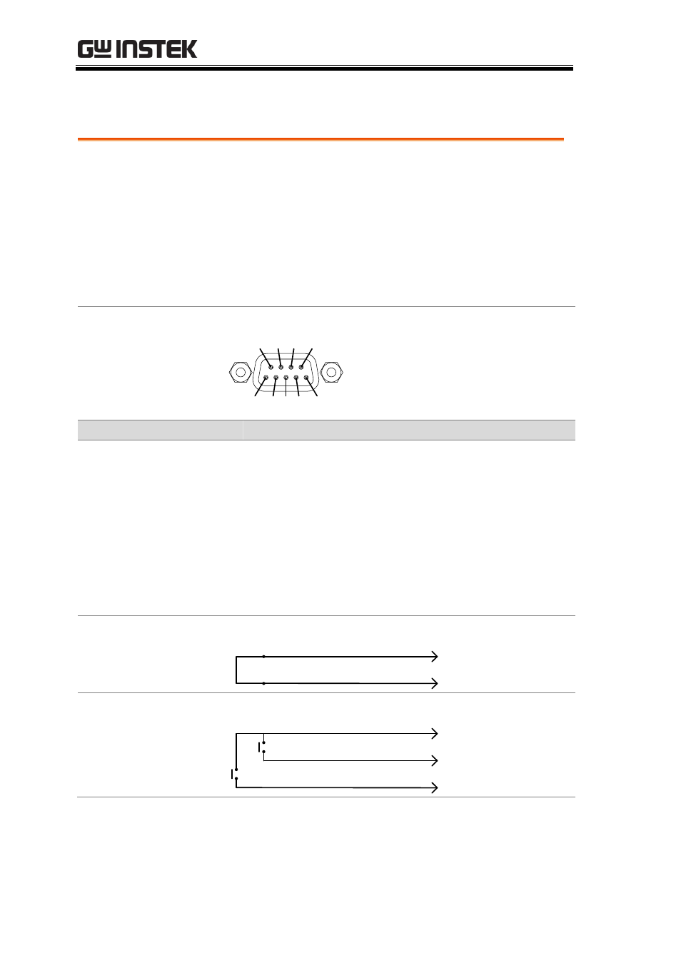
Pin Assignment
6
9
7 8
1 2 3 4 5
Pin name
Pin Description
INTERLOCK1
1
When INTERLOCK is ON, a test is only allowed
to start when both INTERLOCK pins are shorted.
INTERLOCK2
2
INPUT_COM
3
Common input line
INPUT_START
4
Start signal input
INPUT_STOP
5
Stop signal input
OUTPUT_TEST 6
Indicates that a test is in progress
OUTPUT_FAIL
7
Indicates that a test has failed
OUTPUT_PASS 8
Indicates that a test has passed
OUTPUT_COM 9
Common output line
Interlock
connection
PIN 2 INTERLOCK2
PIN 1 INTERLOCK1
Input Connection
PIN 5 INPUT_STOP
PIN 3 INPUT_COM
PIN 4 INPUT_START
- GDB-03 (99 pages)
- GLA-1000 Series User Manual (111 pages)
- GLA-1000 Series Quick start guide (20 pages)
- GOS-630FC (20 pages)
- GOS-635G (36 pages)
- GOS-6000 Series (27 pages)
- GOS-6103C (30 pages)
- GOS-6100 Series (30 pages)
- GRS-6000A Series (51 pages)
- GDS-122 Installation Guide (4 pages)
- GDS-122 User Manual (52 pages)
- GDS-2000A series CAN/LIN bus User Manual (18 pages)
- GDS-2000A series Quick start guide for DS2-FGN (6 pages)
- GDS-2000A series Freewave User Manual (26 pages)
- GDS-2000A series Quick start guide for Logic analyzer option (18 pages)
- GDS-2000A series Quick start quide for DS2-LAN (2 pages)
- GDS-2000A series Option User Manual (80 pages)
- GDS-2000A series User Manual (261 pages)
- GDS-2000A series Programming Manual (272 pages)
- GDS-2000A series Single sheet for LA Quick start guide (2 pages)
- GBS-1000 Series Programming Manual (88 pages)
- GBS-1000 Series User Manual (187 pages)
- GDS-1000-U Series firmware upgrade (1 page)
- GDS-1000-U Series Programming Manual (70 pages)
- GDS-1000-U Series Quick start guide (2 pages)
- GDS-1000-U Series User Manual (133 pages)
- GDS-1000A-U Series Programming Manual (88 pages)
- GDS-1000A-U Series Quick start guide (2 pages)
- GDS-1000A-U Series User Manual (148 pages)
- GDS-3000 Series GCP-530/1030 current probe User Manual (40 pages)
- GDS-3000 Series GDP-025/050/100 differential probe User Manual (21 pages)
- GDS-3000 Series DS3-PWR Power analysis manual (37 pages)
- GDS-3000 Series User Manual (209 pages)
- GDS-3000 Series Programming Manual (103 pages)
- GDS-3000 Series DS3-SBD Serial Bus decode (29 pages)
- GDS-3000 Series GKT-100 deskew fixture User Manual (1 page)
- GDS-3000 Series GUG-001, GPIB to USB adapter User Manual (15 pages)
- GDS-300 Series User Manual (188 pages)
- GDS-300 Series Programming Manual (139 pages)
- GDS-300 Series Quick start guide (21 pages)
- GRF-3300 Series Student Manual (26 pages)
- GRF-3300 Series Teacher Manual (26 pages)
- GRF-1300A (124 pages)
- GSP-810 User Manual (40 pages)
- GSP-810 Software Manual (3 pages)