Scaling and calibration, Scaling and calibration 85 – Watlow CAS200 User Manual
Page 97
CAS200 User’s Guide
Chapter 5: Troubleshooting and Reconfiguring
Watlow Anafaze
85
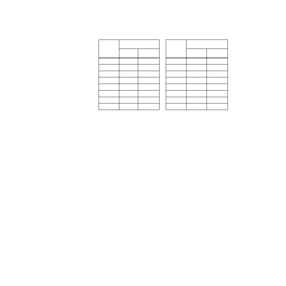
Table 5.6
Resistor Locations for CAS200
Voltage Inputs
Scaling and Calibration
The scanner provides offset calibration for thermocouples
and offset and span (gain) calibration for linear and pulse
inputs. In order to scale linear input signals, you must:
1.
Install appropriate scaling resistors. (Contact Watlow
Anafaze’s Customer Service Department for more
information about installing scaling resistors.)
2.
Select the display format. The smallest possible range
is -.9999 to +3.0000; the largest possible range is -9999
to 30000.
3.
Enter the appropriate scaling values for your process.
See Chapter 6, Linear Scaling Examples on page 87.
Channel
Resistor Locations
Channel
Resistor Locations
RC
RD
RC
RD
1
R58
R42
9
R57
R41
2
R56
R40
10
R55
R39
3
R54
R38
11
R53
R37
4
R52
R36
12
R51
R35
5
R50
R34
13
R49
R33
6
R48
R32
14
R47
R31
7
R46
R30
15
R45
R29
8
R44
R28
16
R43
R27
- 12LS Controller (111 pages)
- 8LS Controller (140 pages)
- 8PID Controller (55 pages)
- Addendum to EZwarePlus (50 pages)
- ANASCAN (62 pages)
- ANASOFT (95 pages)
- ANAWIN 2 (154 pages)
- ANAWIN 3 (23 pages)
- Calibrating Watlow Series 988 Family Process Controls (19 pages)
- CAS (98 pages)
- CLS (180 pages)
- CLS200 (251 pages)
- CLS200, MLS300 and CAS200 (92 pages)
- Control Console (12 pages)
- CPC400 (230 pages)
- DIN-A-MITE Style A (9 pages)
- DIN-A-MITE Style B (14 pages)
- DIN-A-MITE Style C (22 pages)
- DIN-A-MITE Style D (9 pages)
- DIN-Mount Adapter Instruction Sheet, Rev A (1 page)
- Dual DAC (4 pages)
- EM Gateway (28 pages)
- E-Safe Hybrid Relay Rev B (4 pages)
- E-SAFE II Hybrid Power Switch (4 pages)
- EZwarePlus Programming (264 pages)
- EZ-ZONE PM (111 pages)
- EZ-ZONE PM PID (125 pages)
- EZ-ZONE PM Express Limit (34 pages)
- EZ-ZONE PM Express (35 pages)
- EZ-ZONE PM Integrated Controller (181 pages)
- EZ-ZONE RM Limit Module Rev C (127 pages)
- EZ-ZONE RMA Modul (79 pages)
- EZ-ZONE RMC (236 pages)
- EZ-ZONE RME (124 pages)
- EZ-ZONE RMH (161 pages)
- EZ-ZONE RUI/Gateway (62 pages)
- EZ-ZONE RM-Scanner-Modul (140 pages)
- EZ-ZONE ST (97 pages)
- F4 External Event Board - Rev.B (2 pages)
- HG Series Mercury Displacement Relay (6 pages)
- LogicPro (296 pages)
- Mercury Relay or MDR Retrofit (13 pages)
- MICRODIN (24 pages)
- MICRODIN (106 pages)