System wiring, System wiring 14, Figure 2.6— mounting dimensions 14 – Watlow CAS200 User Manual
Page 26
Chapter 2: Installation
CAS200 User’s Guide
14
Watlow Anafaze
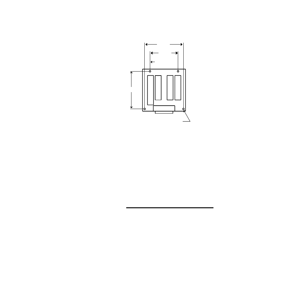
Figure 2.6
Mounting Dimensions
System
Wiring
Successful installation and operation of the alarm scanner
can depend on placement of the components and on
selection of the proper cables, sensors, and peripheral
components.
Routing and shielding of sensor wires and proper
grounding of components can insure a robust system. This
section includes wiring recommendations, instructions for
proper grounding and noise suppression, and
considerations for avoiding ground loops.
∫
WARNING!
To reduce the risk of electrical shock, fire, and
equipment damage, follow all local and national
electrical codes. Correct wire sizes, fuses and
thermal breakers are essential for safe operation
of this equipment.
Standoffs, 4 places
for use with #6-32 screws
0.50 in.
2.60 in.
3.60 in.
3.40 in.
- 12LS Controller (111 pages)
- 8LS Controller (140 pages)
- 8PID Controller (55 pages)
- Addendum to EZwarePlus (50 pages)
- ANASCAN (62 pages)
- ANASOFT (95 pages)
- ANAWIN 2 (154 pages)
- ANAWIN 3 (23 pages)
- Calibrating Watlow Series 988 Family Process Controls (19 pages)
- CAS (98 pages)
- CLS (180 pages)
- CLS200 (251 pages)
- CLS200, MLS300 and CAS200 (92 pages)
- Control Console (12 pages)
- CPC400 (230 pages)
- DIN-A-MITE Style A (9 pages)
- DIN-A-MITE Style B (14 pages)
- DIN-A-MITE Style C (22 pages)
- DIN-A-MITE Style D (9 pages)
- DIN-Mount Adapter Instruction Sheet, Rev A (1 page)
- Dual DAC (4 pages)
- EM Gateway (28 pages)
- E-Safe Hybrid Relay Rev B (4 pages)
- E-SAFE II Hybrid Power Switch (4 pages)
- EZwarePlus Programming (264 pages)
- EZ-ZONE PM (111 pages)
- EZ-ZONE PM PID (125 pages)
- EZ-ZONE PM Express Limit (34 pages)
- EZ-ZONE PM Express (35 pages)
- EZ-ZONE PM Integrated Controller (181 pages)
- EZ-ZONE RM Limit Module Rev C (127 pages)
- EZ-ZONE RMA Modul (79 pages)
- EZ-ZONE RMC (236 pages)
- EZ-ZONE RME (124 pages)
- EZ-ZONE RMH (161 pages)
- EZ-ZONE RUI/Gateway (62 pages)
- EZ-ZONE RM-Scanner-Modul (140 pages)
- EZ-ZONE ST (97 pages)
- F4 External Event Board - Rev.B (2 pages)
- HG Series Mercury Displacement Relay (6 pages)
- LogicPro (296 pages)
- Mercury Relay or MDR Retrofit (13 pages)
- MICRODIN (24 pages)
- MICRODIN (106 pages)