Cas200 voltage inputs, Cas200 voltage inputs 84 – Watlow CAS200 User Manual
Page 96
Chapter 5: Troubleshooting and Reconfiguring
CAS200 User’s Guide
84
Watlow Anafaze
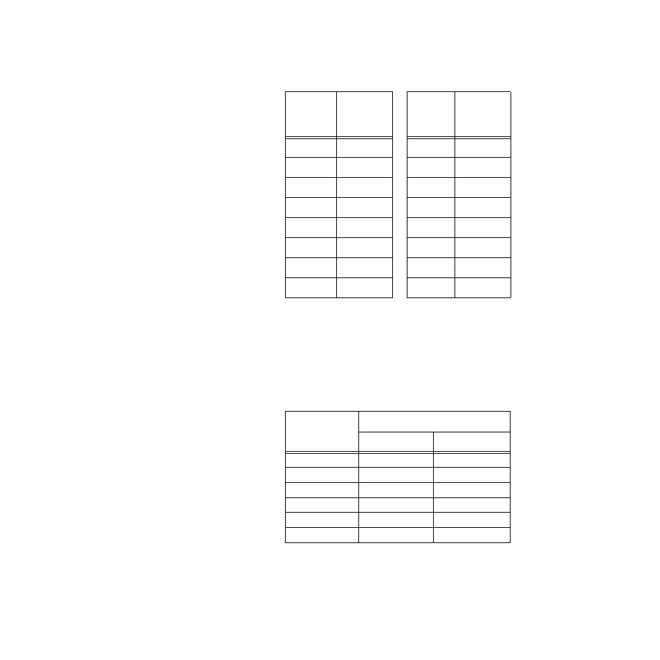
Table 5.4
Resistor Locations for CAS200
Current Inputs
CAS200 Voltage Inputs
For each voltage input on a CAS200 scanner, you must
install two resistors. The resistance must be correct for the
expected input range. Install the resistors in the listed
locations.
Table 5.5
Resistor Values for CAS200
Voltage Inputs
Resistor tolerance:
±
0.1%
Channel
Resistor
Location
RD
Channel
Resistor
Location
RD
1
R42
9
R41
2
R40
10
R39
3
R38
11
R37
4
R36
12
R35
5
R34
13
R33
6
R32
14
R31
7
R30
15
R29
8
R28
16
R27
Input Range
Resistor Values
RC
RD
0 - 100mVdc
499
Ω
750
Ω
0 - 500mVdc
5.49k
Ω
750
Ω
0 - Vdc
6.91k
Ω
422.0
Ω
0 - 5Vdc
39.2k
Ω
475.0
Ω
0 - 10Vdc
49.9k
Ω
301.0
Ω
0 - 12Vdc
84.5k
Ω
422.0
Ω
See also other documents in the category Watlow Sensors:
- 12LS Controller (111 pages)
- 8LS Controller (140 pages)
- 8PID Controller (55 pages)
- Addendum to EZwarePlus (50 pages)
- ANASCAN (62 pages)
- ANASOFT (95 pages)
- ANAWIN 2 (154 pages)
- ANAWIN 3 (23 pages)
- Calibrating Watlow Series 988 Family Process Controls (19 pages)
- CAS (98 pages)
- CLS (180 pages)
- CLS200 (251 pages)
- CLS200, MLS300 and CAS200 (92 pages)
- Control Console (12 pages)
- CPC400 (230 pages)
- DIN-A-MITE Style A (9 pages)
- DIN-A-MITE Style B (14 pages)
- DIN-A-MITE Style C (22 pages)
- DIN-A-MITE Style D (9 pages)
- DIN-Mount Adapter Instruction Sheet, Rev A (1 page)
- Dual DAC (4 pages)
- EM Gateway (28 pages)
- E-Safe Hybrid Relay Rev B (4 pages)
- E-SAFE II Hybrid Power Switch (4 pages)
- EZwarePlus Programming (264 pages)
- EZ-ZONE PM (111 pages)
- EZ-ZONE PM PID (125 pages)
- EZ-ZONE PM Express Limit (34 pages)
- EZ-ZONE PM Express (35 pages)
- EZ-ZONE PM Integrated Controller (181 pages)
- EZ-ZONE RM Limit Module Rev C (127 pages)
- EZ-ZONE RMA Modul (79 pages)
- EZ-ZONE RMC (236 pages)
- EZ-ZONE RME (124 pages)
- EZ-ZONE RMH (161 pages)
- EZ-ZONE RUI/Gateway (62 pages)
- EZ-ZONE RM-Scanner-Modul (140 pages)
- EZ-ZONE ST (97 pages)
- F4 External Event Board - Rev.B (2 pages)
- HG Series Mercury Displacement Relay (6 pages)
- LogicPro (296 pages)
- Mercury Relay or MDR Retrofit (13 pages)
- MICRODIN (24 pages)
- MICRODIN (106 pages)