Mounting, Location, Recommended tools – Watlow CAS200 User Manual
Page 22: Panel hole cutters, Mounting 10, Location 10, Recommended tools 10, Figure 2.2— clearance recommendations 10
Chapter 2: Installation
CAS200 User’s Guide
10
Watlow Anafaze
Mounting
We recommend you mount the scanner in a panel not more
than 0.2 inches thick.
∫
WARNING!
To reduce the risk of fire or electric shock, install
the CAS200 in a controlled environment,
relatively free of contaminants.
Location
Install the scanner in a location free from excessive (>50°C)
heat, dust, and unauthorized handling.
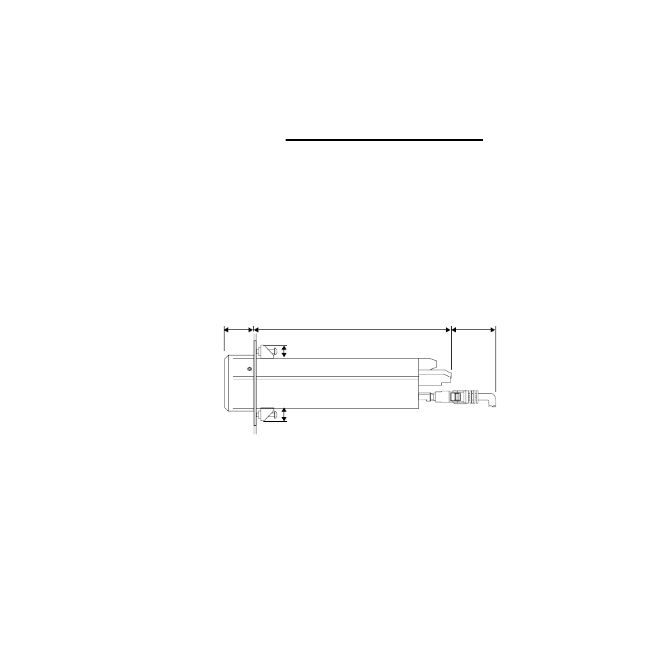
Ensure there is enough clearance for mounting brackets,
terminal blocks, and cable and wire connections; the
scanner extends 7.0 in. behind the panel face and the screw
brackets extend 0.5 in. above and below it. Allow an
additional 1 to 3 inches for the SCSI cable.
Figure 2.2
Clearance Recommendations
Recommended Tools
Use these tools to install the CAS200 series scanner and
TB50:
Panel Hole Cutters:
Use any of the following tools to cut a hole of the
appropriate size in the panel.
•
Jigsaw and metal file, for stainless steel and
heavyweight panel doors.
•
Greenlee 1/8 DIN rectangular punch (Greenlee part
#600-68), for most panel materials and thicknesses.
•
Nibbler and metal file, for aluminum and lightweight
panel doors.
1.00 in.
(25 mm)
Bezel
7.00 in.
(178 mm)
2.00 in.*
(51 mm)
0.50 in.
0.50 in.
(13 mm)
(13 mm)
Steel Case
Terminals
SCSI Cable
*1.00 in. with right-angle SCI cable.