Serial communications, Eia/tia-232 interface, Jumpers in eia/tia-232 connectors – Watlow CAS200 User Manual
Page 37: Serial communications 25, Eia/tia-232 interface 25, Table 2.3— eia/tia-232 connections 25
CAS200 User’s Guide
Chapter 2: Installation
Watlow Anafaze
25
NOTE!
When mixing current inputs with low voltage in-
puts (thermocouples or voltage inputs less than
one volt), connect the current signal to the IN+
and Ref Com terminals. When no low voltage sen-
sors are used, the current inputs can be wired to
the IN+ and Com terminals on the TB1.
Serial
Communications
The CAS200 series scanners are factory-configured for
EIA/TIA-232 communications unless otherwise specified
when purchased. However, the communications are
jumper-selectable, so you can switch between EIA/TIA-232
and EIA/TIA-485. See Changing Communications on page
81.
EIA/TIA-232 Interface
EIA/TIA-232 provides communication to the serial port of
an IBM PC or compatible computer. It is used for single-
scanner installations where the cable length does not
exceed 50 feet (15 m).
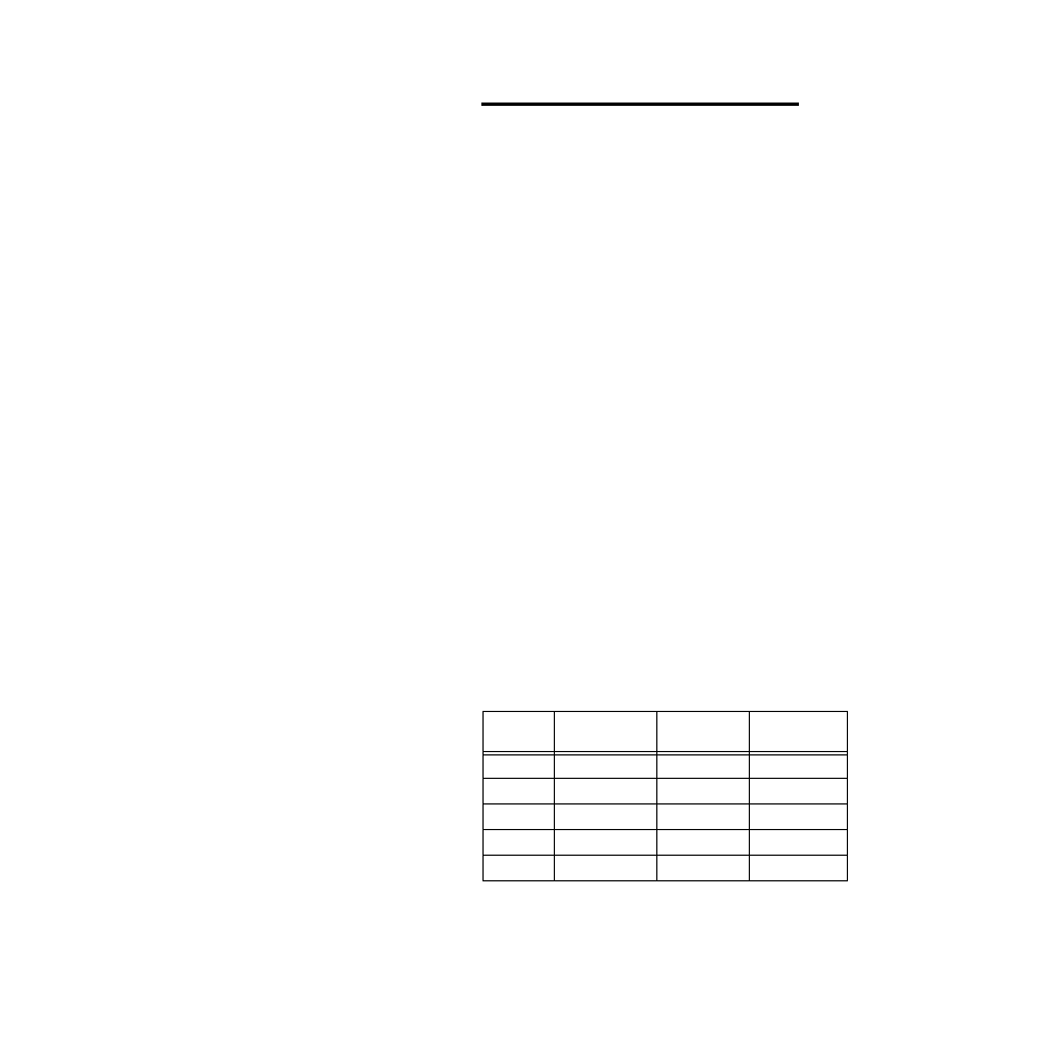
The EIA/TIA-232 interface is a standard three-wire
interface. Table 2.3 shows EIA/TIA-232 connections for 25-
pin and 9-pin connectors or cables that are supplied by the
factory.
If you are using EIA/TIA-232 communications with
grounded thermocouples, use an optical isolator between
the scanner and the computer to prevent ground loops.
EIA/TIA-232 may be used to connect a computer through a
232-to-485 converter to an EIA/TIA-485 communications
network with up to 32 CAS200 scanners.
Table 2.3
EIA/TIA-232 Connections
Jumpers in EIA/TIA-232 Connectors
Some software programs and some operator interface
terminals require a clear to send (CTS) signal in response
Wire
Color
CAS200
TB1
DB 9
Connector
DB 25
Connector
White
TX Pin 26
RX Pin 2
RX Pin 3
Red
RX Pin 25
TX Pin 3
TX Pin 2
Black
GND Pin 23
GND Pin 5
GND Pin 7
Green
GND Pin 24
N/U Pin 9
N/U Pin 22
Shield
N/C
GND Pin 5
GND Pin 7