Thermocouple connections, Thermocouple connections 23, Figure 2.10— wiring thermocouple inputs 23 – Watlow CAS200 User Manual
Page 35
CAS200 User’s Guide
Chapter 2: Installation
W
atlow Anafaze
23
The scanner accepts the following inputs without any
special scaling resistors:
•
J, K, T, S, R, and B thermocouples.
•
Linear inputs with ranges between -10 and 60 mV.
Any unused inputs should be set to “SKIP” or jumpered to
avoid thermocouple break alarms.
Connect signal inputs to TB1 as shown below. Note that
some inputs require scaling resistors that are generally
factory installed.
Thermocouple Connections
Use 18 or 20 AWG thermocouple (T/C) extension wire for
all the thermocouple inputs. Most thermocouple wire is
solid unshielded wire. Use shielded wire if required at your
installation; ground one end only.
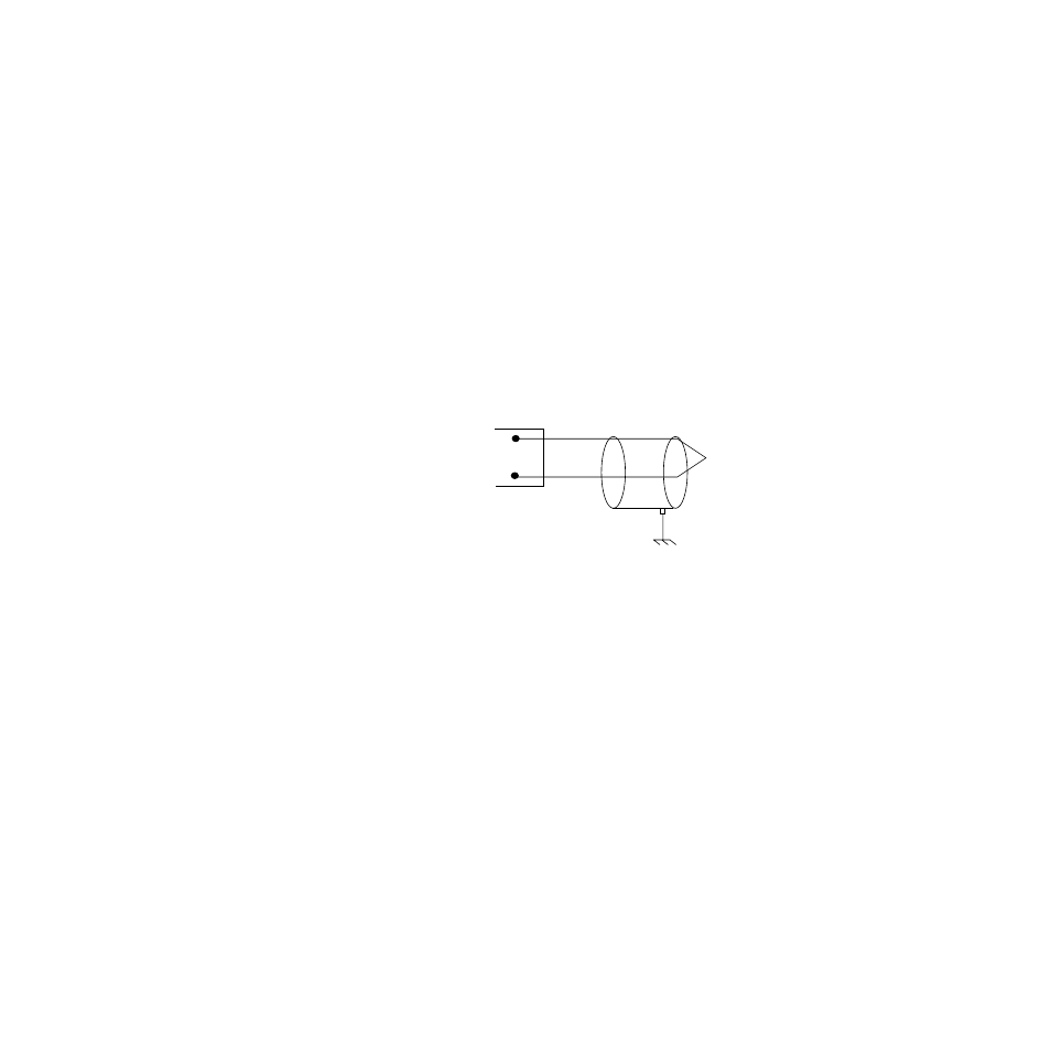
Figure 2.10 Wiring Thermocouple Inputs
Since the CAS200 has single ended inputs, it has little
protection from common mode voltage sources. Therefore,
Watlow Anafaze highly recommends that you use
ungrounded thermocouples with the external
thermocouple sheath electrically connected to earth
ground.
You can use 400 to 500 feet of thermocouple extension wire,
depending on wire type and size, and keep to accuracy and
source impedance specifications. Always install
thermocouple wiring in separate conduit away from AC
power (the 120Vac control supply) and high power (240Vac
or higher) wiring.
White
Red
Type J T/C
Ch # IN +
Shield (if present)
Earth Ground
Com
at Process End