Connecting the tb50 to the cas200, Input wiring, Sensor connection – Watlow CAS200 User Manual
Page 34: Connecting the tb50 to the cas200 22, Input wiring 22, Sensor connection 22, Figure 2.9— sensor connections 22, Warning, Figure 2.9 sensor connections
Chapter 2: Installation
CAS200 User’s Guide
22
Watlow Anafaze
3. Press "Y" for Yes to reset all the parameters. When all
parameters are reset the scanner will display the
following.
Connecting the TB50 to the CAS200
For a CAS200 scanner with the TB50 option:
1.
Connect the SCSI cable to the scanner.
2.
Connect the SCSI cable to the TB50.
Input
Wiring
Sensor Connection
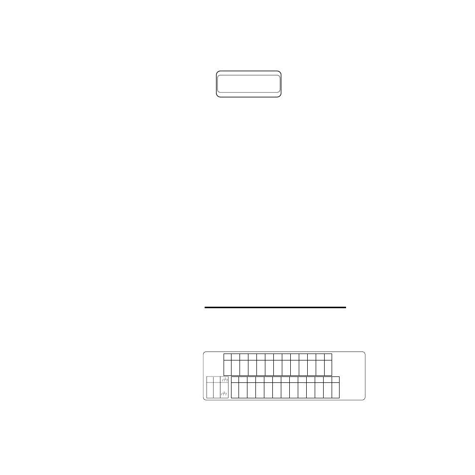
This section describes how to properly install inputs to your
scanner. Inputs refer to thermocouples, current and
voltage Inputs. The scanner can accept any mix of available
input types. Some input types require that special scaling
resistors be installed (generally done by Watlow Anafaze
before the scanner is delivered). All inputs are installed at
the channel input connectors (TB1) at the back of the
scanner. The illustrations below show the connector
locations for the CAS216 scanner.
∫
WARNING!
Never run input leads in bundles with high power
leads.
Figure 2.9
Sensor Connections
Follow the instructions pertaining to the type(s) of input(s)
you are installing.
CHANNEL PROCESS UNITS
CHANNEL NAME ALARM STATUS
01 70°F
CHAN 01
+
-
+V
C
o
m
Gnd
1 3 5 7 9 11 13 15 17 19 21 23 25
C
o
m
CH
1
IN+
CH
2
IN+
C
o
m
CH
3
IN+
CH
4
IN+
Ref
Com
CH
5
IN+
CH
6
IN+
Gnd
/
RXB
RX
/
RXA
CH
7
IN+
CH
8
IN+
2 4 6 8 10 12 14 16 18 20 22 24 26
C
o
m
CH
9
IN+
CH
10
IN+
C
o
m
CH
11
IN+
CH
12
IN+
+5V
Ref
CH
13
IN+
CH
14
IN+
Gnd
/
TXB
TX
/
TXA
CH
15
IN+
CH
16
IN+
TB1
CLS216
CAS200
MADE
IN THE
USA
TB2