Front panel control buttons, Initiator and target sas/sata cable connectors, Sas infusion rear panel – Teledyne LeCroy SAS_SATA InFusion - Users Manual User Manual
Page 18: Bnc input/output connectors, Figure 2 sasinfusion rear panel
Version 2.0
SAS InFusion User Manual
4
LeCroy Corporation
After you have downloaded some scenarios to the SAS InFusion box, the Root menu
shows four items:
•
Box Setup
•
SAS Configuration
•
Start Infusion
•
Infusion Setup
Front Panel
Control
Buttons
The control buttons are located on the right side of the control panel. They consist of two
buttons to navigate LCD menus, the Up and Down buttons, and a Center button to select
menu items.
Initiator and
Target
SAS/SATA
Cable
Connectors
The two external SAS/SATA connectors provide high-speed, differential connections to
the test initiator (host) and target (device-under-test, or for brevity, DUT). These
connectors support the external-to-internal SATA cables provided.
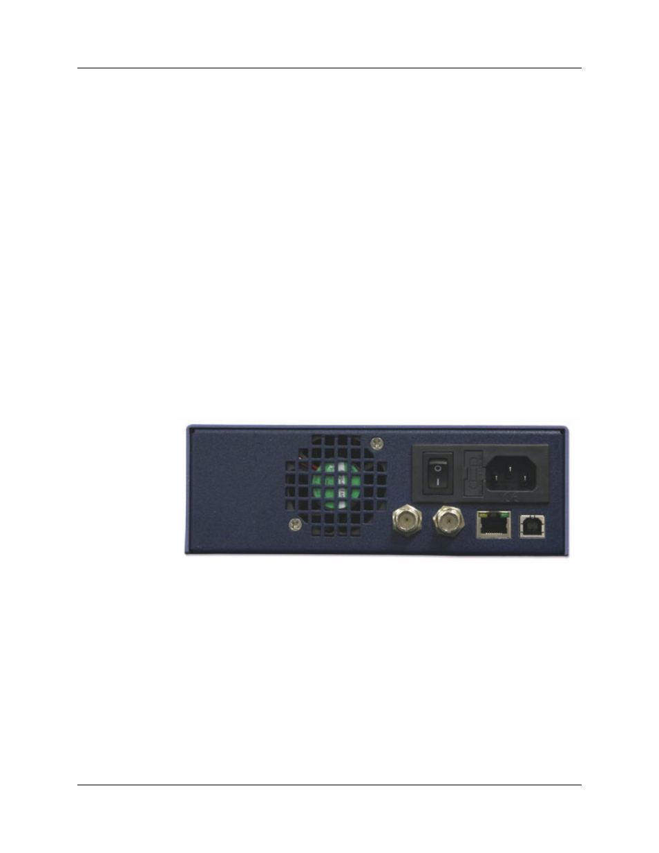
SAS InFusion Rear Panel
The SAS InFusion rear panel consists of two BNC Input/Output connectors, one USB
connector, an Ethernet port, and a power connector (Figure 2).
Figure 2
SASInFusion Rear Panel
BNC
Input/Output
Connectors
The two BNC connectors are ports for Trigger In and Trigger Out signals for the box. They
allow you to daisy-chain the box with other SAS InFusion boxes for multi-link tests. They
also allow you to connect the SAS InFusion box to an external test device, such as an
analyzer or oscilloscope.
The Trigger In signal is used to inject an error or other action into the protocol data stream
at a specific instance in time, while the Trigger Out signal can be asserted when a pattern
match or error injection occurs during SAS InFusion operation.