Gilderfluke&Co 'Smart' Brick Animation Control System User Manual
Page 34
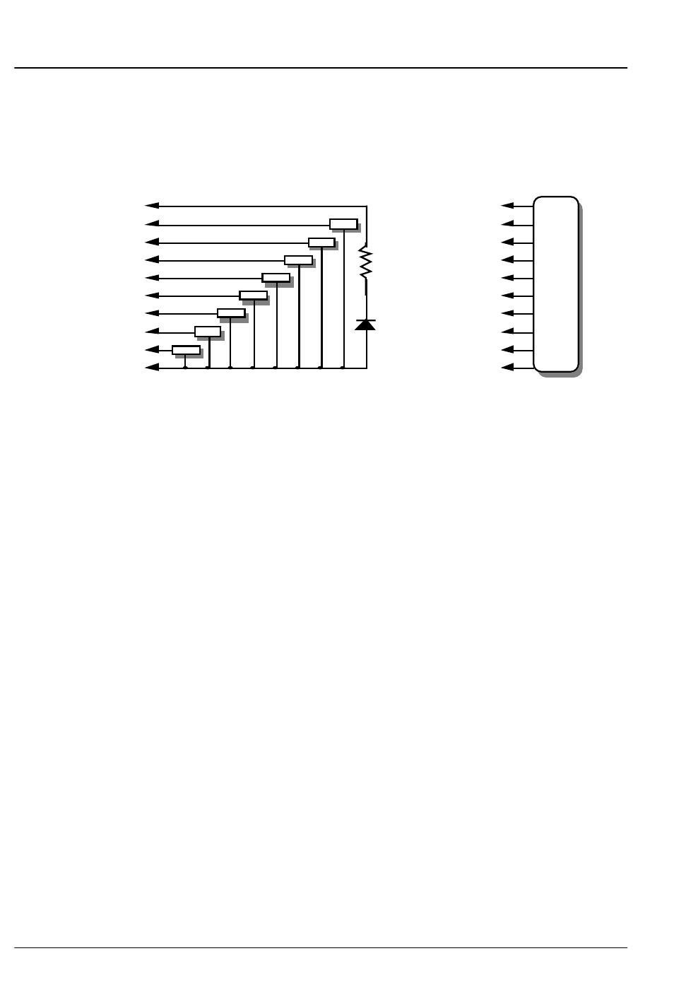
Any eight digital devices or one eight bit analog device can
be connected to any 1/4 J-6 cable as shown. The LED between
the ground (pin #1 brown) wire and supply (pin #10 black) wire
acts as an indicator which is lit if the fuse for that channel is OK:
#1 ground (brown)--
#2 bit 7 (red)--
#3 bit 6 (orange)--
#4 bit 5 (yellow)--
#5 bit 4 (green)--
#6 bit 3 (blue)--
#7 bit 2 (violet)--
#8 bit 1 (grey)--
#9 bit 0 (white)--
#10 supply (black)--
load
load
load
load
load
load
load
load
#1 ground (brown)--
#2 bit 7 (red)--
#3 bit 6 (orange)--
#4 bit 5 (yellow)--
#5 bit 4 (green)--
#6 bit 3 (blue)--
#7 bit 2 (violet)--
#8 bit 1 (grey)--
#9 bit 0 (white)--
#10 supply (black)--
any
eight bit
analog
device
LED
2.2 K ohm
1/4 watt resistor
The supply line for each 1/4 J-6 is fused for one amp. You
should treat each 1/4 J-6 as an individual, and not cross the out-
puts or supply lines from one channel to the lines from any other
channel. Doing this won’t cause any damage, but can reduce
the protection for the outputs that the fuses normally provide.
G
ILDERFLUKE
& C
O
.• 205 S
OUTH
F
LOWER
S
TREET
• B
URBANK
, C
ALIFORNIA
91502 • 818/840-9484 • 800/776-5972 •
FAX
818/840-9485
E
AST
C
OAST
/F
LORIDA
O
FFICE
• 7041 G
RAND
N
ATIONAL
D
RIVE
• S
UITE
128d • O
RLANDO
, F
L
. 32819 • 407/354-5954 •
FAX
407/354-5955
24 of 178