FEC DSP1500 (SAN3) User Manual
Page 71
enFORCE
DSP1500 SAN Unit Operation Manual
PAGE 4-31 (Rev.
4)
Chapter 4: System Setup and Wiring
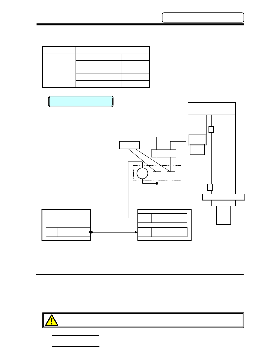
4.14 Maintenance Lock Option
Power Requirements
Voltage
24VDC to disengage brake
Current
Consumption
RM1 Motor
0.5A
RM2 Motor
0.5A
RM3 Motor
0.5A
RM4H Motor
0.8A
RM5 Motor
1.2A
*
When a fixture, heavy enough to pull the press ram down when the servo is not running, is
attached to the press ram use “Servo On” to monitor when to engage/disengage the brake
(maintenance lock). When “Servo On” signal goes high (On) release (disengage) the brake.
*
Under normal circumstances, the brake (maintenance lock) can be engaged/disengaged by wiring
it directly to the “Control Power” circuit; only engaging (locking) on loss of Control Power.
Unless instructed by FEC, System Parameter 00-36 should always be configured for
“Dynamic Hold”.
Setting the “Dynamic Hold” configuration allows the servo motor to
dynamically hold the press ram when stopped. Setting System Parameter 00-36 to “Off” forces
the Maintenance Lock (when equipped) to hold the press ram when the servo stops.
The maintenance lock should be used for maintenance purposes only, not for control.
Using the maintenance lock to control stopping of the press ram will decrease the life of
the lock unit dramatically.
This circuit is shown for reference only and does not guarantee the safe operation
of this press. Safety measures must be examined for each application.
BRAKE CABLE (DPT): (FIELD):
FEC P/N: FEB-1314
(EXTENSION):
FEC P/N: FEB-1609
BRAKE CABLE (DPS): (FIELD):
FEC P/N: FEB-1625
Brake
0V
24V
24 SERVO ON
I/O Connector
X000 SERVO ON
Y001 RELEASE BRAKE
RY
S
S
A
A
N
N
U
U
n
n
i
i
t
t
P
P
L
L
C
C
*PLC I/O shown for
reference only.
P
P
r
r
e
e
s
s
s
s
Reference Circuit
red/grn
blu/grn
A B
BRK
Varister