FEC DSP1500 (SAN3) User Manual
Page 46
enFORCE
DSP1500 SAN Unit Operation Manual
(Rev. 4)
PAGE 4-6
Chapter 4: System Setup and Wiring
M
O T O R
A
C 2 00 - 2 2 0 V
P
L C
T
/ D
SAN3-24SM
1
:
F
G
2
:
W
3
:
V
4
:
U
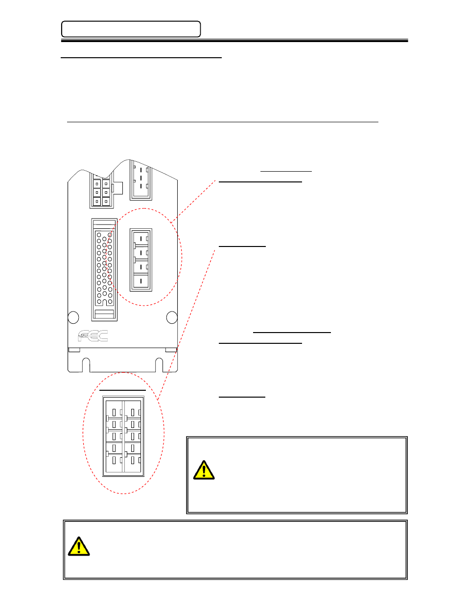
4.4 Input Power Supply Connection(s)
On SAN3 Units, Motor and Control input power is supplied on one connector. On SAN4 Units the
Motor and Control input power can be separated. This allows the removal of motor power without
the press losing its Home Position.
Adequate circuit protection must be provided for the SAN unit input power.
4.4.1 Input Motor & Control (SAN3) / Input Motor Power (SAN4) Connection
Recommended conductor size should be a minimum of #16AWG.
Suggested color code (FEC standard): U – Red, V – White, W – Black, FG – Green.
Wiring Chart
SAN3/4-24S, 24HS, 40S
4:U
3-Phase
3:V
180 ~ 242VAC
2:W
50/60Hz.
1:FG
SAN3/4-120S (Shown Below)
A5:U
B5:U 3-Phase
A4:V B4:V
180 ~ 242VAC
A3:W B3:W
50/60Hz.
A2:NC B2:NC
A1:FG B1:FG
*Connect wires to both the A side and B side.
Mating Connectors
SAN3/4-24S, 24HS, 40S
Manufacture:
AMP
Housing Part No.:
1-178128-4
Contact Part No.:
1-175218-3 (Qty.-4)
SAN3/4-120S
Manufacture:
AMP
Housing Part No.:
1-917659-5
Contact Part No.:
1-917511-3 (Qty.-8)
Install adiquate circuit protection on the input
power feed. (Refer to Appendix A for wiring)
When using a transformer that is not isolated or if
incoming power is known to be noisy, install a filter
in the input power circuit. Recommended Filters:
SAN3/4-24S, 24HS TDK #ZRWT2205-ME
SAN3/4-40S
TDK #ZRWT2210-ME
SAN3/4-120S
TDK #ZRWT2220-ME
If using a SAN4 Unit with separately wired motor and control input circuits be aware
that when motor power is dropped during operation the press does not come to an
immediate stop due to momentum.
If normal operation requires the motor power to be dropped for safety (IE: interruption
of safety gates, etc.) turn the STOP signal off at the same time the motor power is
dropped so that the dynamic braking circuit stops press motion.
SAN3/4-120S
5
4
3
2
1
B A