Enforce, 7 external-control signal connection – FEC DSP1500 (SAN3) User Manual
Page 50
enFORCE
DSP1500 SAN Unit Operation Manual
(Rev. 4)
PAGE 4-10
Chapter 4: System Setup and Wiring
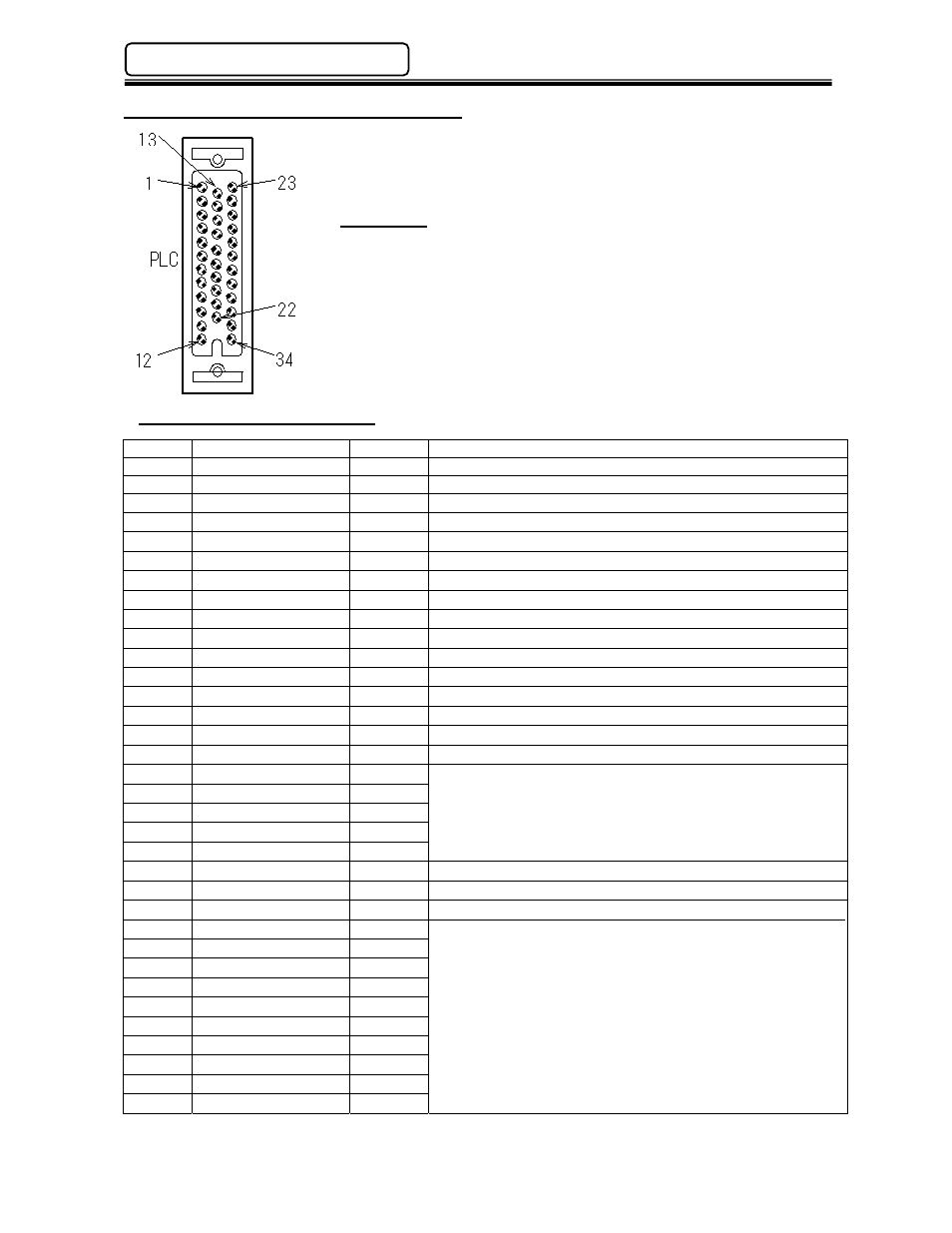
4.7 External-Control Signal Connection
Mating Plug
Manufacturer:Honda Tsushin Kougyo (HONDA)
Vertical Housing Part No.:
MR-34L
Male Insert Part No.:
MR-34M
(See Appendix A for connecting cable part numbers)
4.7.1 PLC Interface (I/O ) Signals [Main Unit Configuration]
IN: Input Signal OUT: Output Signal NC: Normally Closed NO: Normally Open
Pin No.
Signal Name
IN/OUT
Description
1 NOT
USED
No
Connection
Allowed
2 NOT
USED
No
Connection
Allowed
3 NOT
USED
No
Connection
Allowed
4 NOT
USED
No
Connection
Allowed
5 NOT
USED
No
Connection
Allowed
6 NOT
USED
No
Connection
Allowed
7 NOT
USED
No
Connection
Allowed
8 NOT
USED
No
Connection
Allowed
9
NEAR ORIGIN
IN (N.O.) Home sensor input (Used for special applications)
10 NOT
USED
No Connection Allowed
11 NOT
USED
No Connection Allowed
12 NOT
USED
No Connection Allowed
13
IN COMMON
Input signal common. (+12 ~ +24VDC)
14 NOT
USED
No
Connection
Allowed
15
CW LIMIT
IN (N.C.) Clockwise limit sensor input.(Advance limit)
16
CCW LIMIT
IN (N.C.) Counter-clockwise limit sensor input.(Return limit)
17
NOT USED
No Connection Allowed
18
NOT USED
19
NOT USED
20
NOT USED
21
NOT USED
22 NOT
USED
23
OUT COMMON
Output signal common. (0VDV)
24 SERVO
ON
OUT (N.O.) May be used to turn on the optional brake unit (disengage)
No Connection Allowed
25
NOT USED
26
NOT USED
27
NOT USED
28
NOT USED
29
NOT USED
30
NOT USED
31
NOT USED
32
NOT USED
33
NOT USED
34
NOT USED