PASCO EM-8656 AC_DC ELECTRONICS LABORATORY User Manual
Page 99
95
012-05892A
AC/DC Electronics Laboratory
®
➤ NOTE: For quick reference, see the Experiment Notes window. To bring a display to the top,
click on its window or select the name of the display from the list at the end of the Display menu.
Change the Experiment Setup window by clicking on the “Zoom” box or the Restore button in
the upper right hand corner of that window.
➄
The “Sampling Options…” are: Periodic Samples = 200 Hz, Start Condition is Analog Output =
0.01 V and Stop condition = Samples at 200.
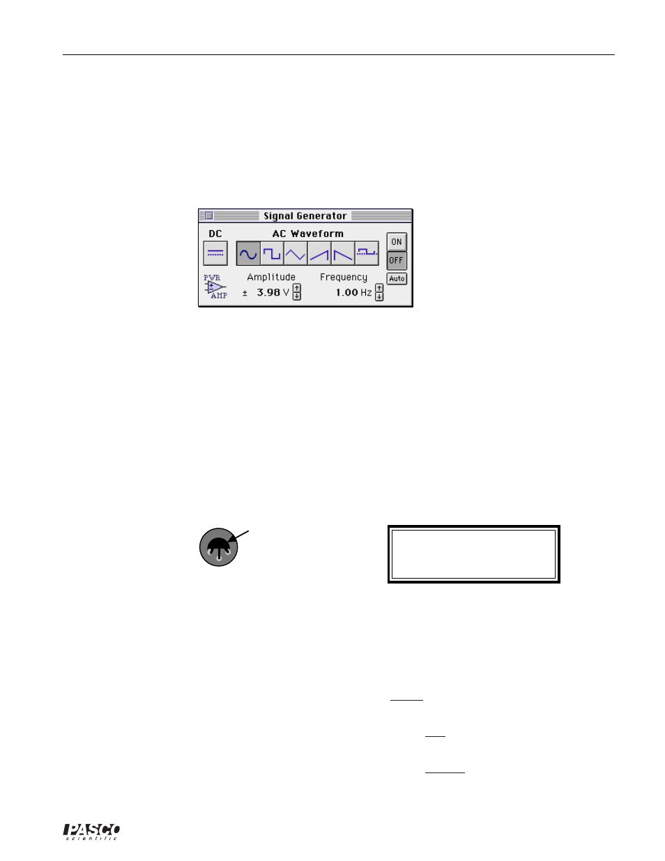
➅
The Signal Generator is set to Amplitude 3.98 V, sine AC waveform, and Frequency 1.00 Hz.
➆
Arrange the Graph display and the Signal Generator window so you can see both of them.
•
The Output Current (vertical axis) is calculated by dividing the voltage drop across the 1 k
Ω
resistor (Analog Channel B) by the resistance. The Input Current (horizontal axis) is calculated
by dividing the voltage drop across the 22 k
Ω
resistor (Analog Channel A) by the resistance.
PART II: Sensor Calibration and Equipment Setup
•
You do not need to calibrate the Voltage Sensor or Power Amplifier.
➀
Insert the 2N3904 transistor into the socket on the AC/DC Electronics Lab Board. The transistor
has a half-cylinder shape with one flat side. The socket has three holes labeled “E” (emitter), “B”
(base) and “C” (collector). When held so the flat side of the transistor faces you and the wire
leads point down, the left lead is the emitter, the middle lead is the base, and the right lead is the
collector.
C = Collector
B = Base
E = Emitter
Socket
2N3904 transistor
Top view of transistor socket
➁
Connect the 1 k
Ω
resistor (brown, black, red) vertically between the component spring at the left
edge of the component area on the AC/DC Electronics Lab Board.
➂
Connect the 22 k
Ω
resistor (red, red, orange) vertically between the component springs to the
right of 1 k
Ω
resistor.
➃
Connect a wire lead between the component spring next to the emitter terminal of the transistor,
and the component spring at the top end of the 1 k
Ω
resistor.
➄
Connect another wire lead betweeen the component spring next to the base terminal of the
transistor, and the component spring at the top end of the 22 k
Ω
resistor.
➅
Connect another wire lead betweeen the component spring next to the collector terminal of the
transistor, and the component spring next to the top banana jack.
➤ CAUTION: Connecting the
transistor incorrectly can destroy
the transistor.