Exp 8- capacitors in circuits – PASCO EM-8656 AC_DC ELECTRONICS LABORATORY User Manual
Page 123
119
012-05892A
AC/DC Electronics Laboratory
®
Analysis
First circuit:
➀
node (1,3):
0.1 mA
node (1,2,5):
0.0 mA
node (3,4,5):
-0.1 mA
node (2,4):
0.0 mA
➁
loop (1,5,3):
0.001 V
loop (1,2,4,3):
0.001 V
loop (5,2,4):
0.000 V
loop (batt,1,2):
0.001 V
loop (batt,3,4):
0.000 V
loop (batt,1,5,4):
0.001 V
loop (batt,3,5,2):
0.000 V
Second circuit:
➀
node (2,3,4):
-0.1 mA
node (b1,3,5):
0.1 mA
➁
loop (b1,1,2,3)
0.001 V
loop (b2,5,3,4)
0.001 V
loop (b1,1,2,4,b2,5)
0.002 V
Discussion
Within the experimental uncertainty of the measuring
device used (a DMM) Kirchoff’s Rules are verified. The
net current flowing into or out of any junction is approxi-
mately zero, and the sum of the voltages around any loop
is approximately zero.
Exp 8- Capacitors in Circuits
Procedure
➃
The rate at which the capacitor loses its charge de-
pends on the impedance of the meter used to measure
the voltage, as well as on the size of the capacitor. For
this reason, most analog meters are not sufficient for
this lab.
➄
Voltage
Time
Voltage
Time
Charging
Discharging
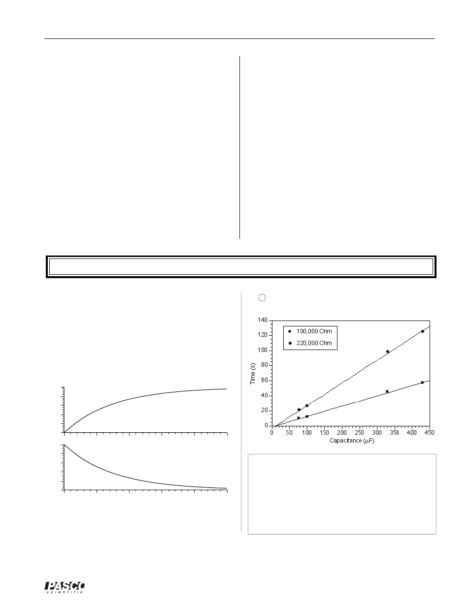
➆
-11
➤NOTES:
➀➁
Charging: t = - R C ln(1-V/V
o
)
Discharging: t = - R C ln(V/V
o
)
In either case, the time is linearly dependent on
both resistance and capacitance.
➂
Parallel: C
p
= C
1
+ C
2
Series: 1/C
s
= 1/C
1
+ 1/C
2