PASCO EM-8656 AC_DC ELECTRONICS LABORATORY User Manual
Page 73
69
012-05892A
AC/DC Electronics Laboratory
®
➄
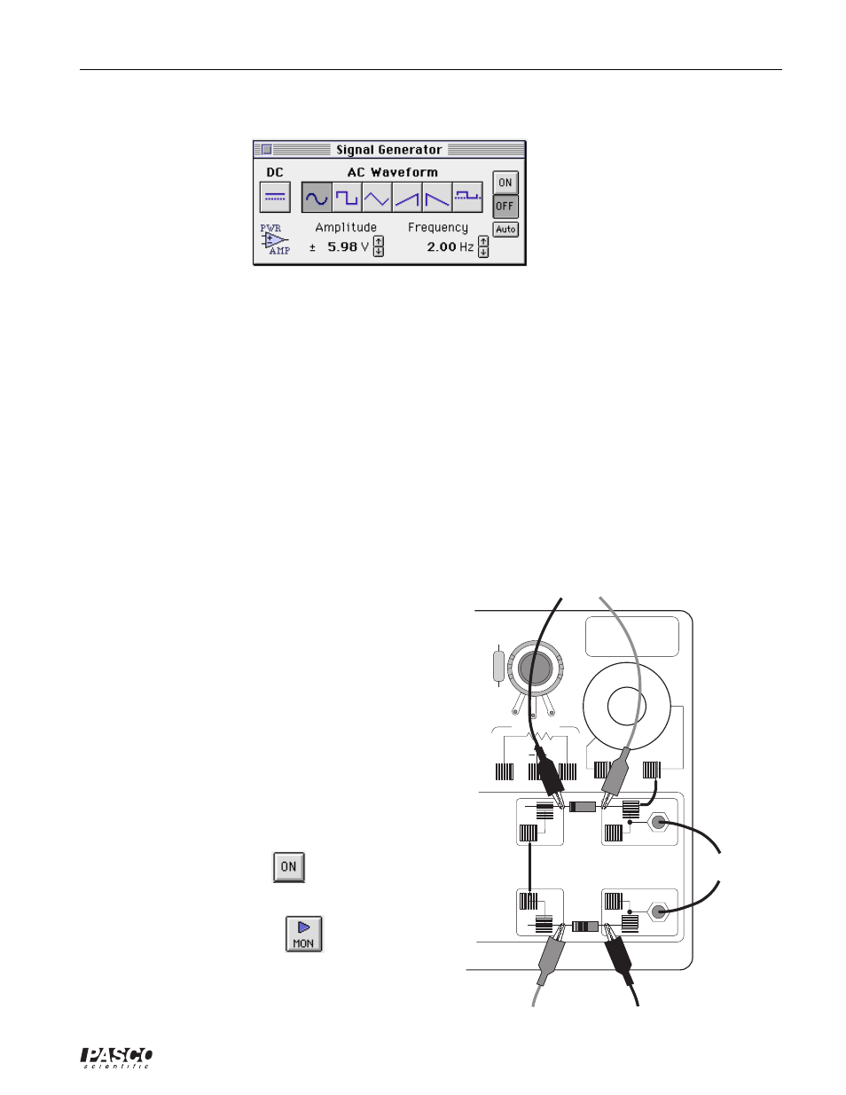
The Signal Generator is set to output 6.00 V, sine AC waveform, at 2.00 Hz.
➅
The periodic sampling rate is determined by the Scope display Sweep Speed.
➆
Arrange the Scope display and the Signal Generator window so you can see both of them.
PART II: Sensor Calibration and Equipment Setup
•
You do not need to calibrate the Voltage Sensors or Power Amplifier.
➀
Connect the 1N-4007 diode (black with gray stripe at one end) between the component spring
next to the top banana jack and the component spring to the left of the banana jack. Arrange the
diode so the gray stripe is at the left end.
➁
Connect the 1 k
Ω
resistor (brown, black, red) between the component spring next to the bottom
banana jack and the component spring to the left of the bottom banana jack.
➂
Connect a 5 inch wire lead between the component spring at the left end of the diode and the
component spring at the left end of the 1 k
Ω
resistor.
➃
Put alligator clips on the banana plugs of both
voltage sensors. Connect the alligator clips of the
Channel A voltage sensor to the wires at both ends
of the diode.
➄
Connect the alligator clips of the Channel B voltage
sensor to the wires at both ends of the 1 k
Ω
resistor.
➅
Connect banana plug patch cords from the output of
the Power Amplifier to the banana jacks on the AC/
DC Electronics Lab Board.
PART IIIA: Data Recording - Rectifying a
Sine Wave with a Diode
➀
Turn on the power switch on the back of the power
amplifier.
➁
Click the “ON” button (
) in the Signal
Generator window.
➂
Click the “MON” button (
) to begin data
monitoring.
EM-8656
AC/DC ELECTRONICS LABORATORY
3 VOLTS MAX
C
W
3.3
Ω
KIT NO.
to Power Amp
Diode
Res
to Channel B
to Channel A