PASCO EM-8656 AC_DC ELECTRONICS LABORATORY User Manual
Page 89
85
012-05892A
AC/DC Electronics Laboratory
®
Experiment 17: Transistor Lab 1 – The NPN
Transistor as a Digital Switch
EQUIPMENT NEEDED:
– Computer and Science Workshop™ Interface
– Power Amplifier (CI-6552A)
– Voltage Sensor (CI-6503)
– AC/DC Electronics Lab Board (EM-8656)
– Regulated DC power supply of at least +5 Volts
– Banana plug patch cords (such as SE-9750)
Purpose
The purpose of this experiment is to investigate how the npn transistor operates as a digital switch.
Theory
The transistor is the essential ingredient of every electronic circuit, from the simplest amplifier or
oscillator to the most elaborate digital computer. Integrated circuits (IC’s), which have largely
replaced circuits constructed from individual transistors, are actually arrays of transistors and
other components built from a single wafer-thin piece or “chip” of semiconductor material.
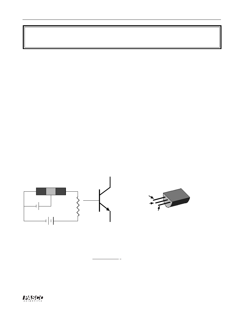
The transistor is a semiconductor device that includes two p-n junctions in a sandwich configura-
tion which may be either p-n-p or, as in this activity, n-p-n. The three regions are usually called
the emitter, base, and collector.
n
p
n
collector
base
emitter
Vsupply
n-p-n transistor
+
+
Vbase
Rload
Base
Collector
Emitter
npn transistor symbol
Emitter
Base
Collector
Transistor package
In a transistor circuit, the current through the collector “loop” is controlled by the current to the base.
The collector voltage can be considerably larger than the base voltage. Therefore, the power
dissipated by the resistor may be much larger than the power supplied to the base by its voltage
source. The device functions as a power amplifier (as compared to a step-up transformer, for
example, which is a voltage amplifier but not a power amplifier). The output signal can have
more power in it than the input signal. The extra power comes from an external source (the
power supply). A transistor circuit can amplify current or voltage. The circuit can be a constant
current source or a constant voltage source.